
Specifications
3
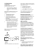
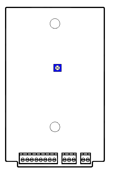
STATIONARY
BREAK
MAKE
RING
TIP
SWITCH
GND OUT
POWER
POWER
MIC SHIELD
LO Z1
HI Z
LO Z2
J3 J2 J1
V-9939B
Volume
Control
Power Connections
___ 1. Unplug power supply.
___ 2. Connect -24VDC "A" battery (may be
referred to as "-" or "talk battery") from
power supply to one of the PWR
terminals on the V-9939B.
___3. Connect -24VDC Ground ("A" ground,
"+" or "talk" ground) from power supply
to the other power terminal. This GND
should be properly grounded to an earth
ground to alleviate hum on the system.
Connecting Arrangements
NOTE: Place a check by the Arrangement
being used and proceed to the Figure
indicated for step-by-step instructions.
___1. Stand alone page system: Proceed to
Figure 3.
___2. Override an individual zone using a
V-2001A: Proceed to Figure 4.
Figure 2 - Location and Connection
Designations
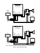
WIRING INSTRUCTIONS (For Figure 3)
Place a check by each step as it is completed:
___1. Mount the V-1094A near the V-9939B or
at the main frame.
___2. Connect Tip of the V-9939B to Tip of the
V-1094A input.
___3. Connect Ring of the V-9939B to Ring of
the V-1094A input.
___4. Connect Tip of the V-1094A output to
the Tip side of all the one-way amplified
speaker assemblies.
___5. Connect Ring of the V-1094A output to
the Ring side of all the speakers.
___6. Connect the microphone:
___a. Connect the audio common lead
shield from the microphone to the MC
terminal of the V-9939B. (This shield
should be strapped to power supply
GND).
___b. Connect the other microphone audio
lead to HZ if using a high impedance
microphone; if using a low impedance
balanced microphone, connect (+)
lead to LZ1 and the (-) lead to LZ2.
___c. Connect one side of the microphone
push to talk switch to the V-9939B SW
terminal.
___d. Connect the other side of the push to
talk switch to the GND OUT terminal.
___7. Connect -24VDC from the power supply
to the -24VDC terminal of the V-1094A.
___8. Connect Ground (+) of the power supply
to the Ground terminal of the V-1094A.
___9. Connect -24VDC from the power supply
to the -24VDC terminal (or the white
lead) of each speaker assembly.
___10. Connect Ground of the power supply to
the Ground terminal (or the black lead)
of each speaker assembly.
___11. Plug in the power supply.
___12. Volume adjustment:
___ a. Set the V-1094A volume control to 5.
___ b. Turn the screwdriver adjustable
volume control on the V-9939B about
1/2 of the way clockwise.
___ c. Verify all speaker controls are set at
1/2.
___ d. Speak through the microphone and
adjust the V-1094A for the proper
system level.
___ e. Speak through the microphone and
adjust the individual speakers to the
required levels.