
Specifications
5
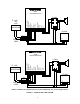
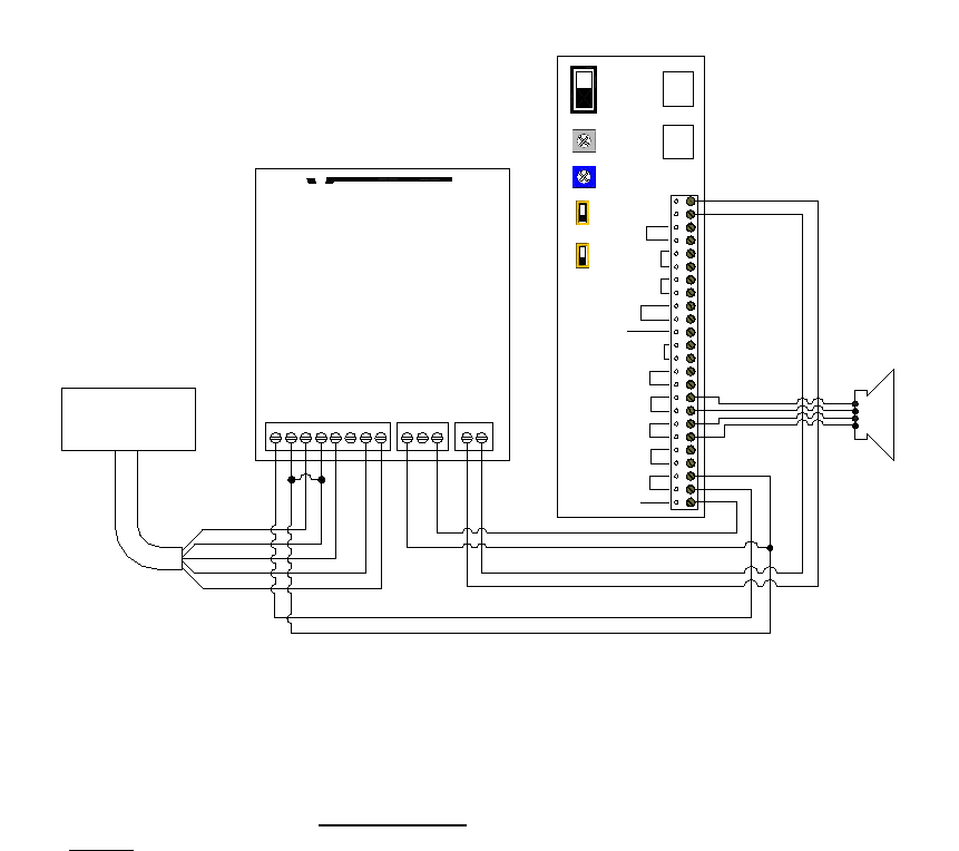
FIGURE 4 – OVERRIDE A SINGLE ZONE WITH A V-2001A
WIRING INSTRUCTIONS (For Figure 4)
Place a check by each step as it is completed:
___ 1. IMPORTANT: Complete installation and
testing of your page control unit and
speakers before adding the microphone
adapter.
___ 2. Mount the V-2001A near the microphone
adapter.
___ 3. Connect Tip of the V-9939B to PAGE
TIP.
___ 4. Connect Ring of the V-9939B to PAGE
RING.
___ 5. Connect the GND of the V-2001A to
terminal STATIONARY on the
microphone.
___ 6. Connect the PPCC of the V-2001A to
terminal MAKE of the microphone
adapter.
___ 7. Disconnect Tip of the audio pair to the
speakers on the zone being overridden
from the Page Control unit and connect
it to the PAGE + MUSIC of the V-2001A.
___ 8. Disconnect Ring of the audio pair to the
speakers from the Page Control unit and
connect it to the PAGE + MUSIC of the
V-2001A.
____9. Connect the MUSIC INPUT of the
V-2001A to one side of the output pair
from the page control unit for the zone
to be overridden.
___10. Connect the MUSIC INPUT of the
V-2001A to the other side of the output
pair from the page unit for the zone
being used.
___11. Connect the microphone:
___a. Connect the audio common lead
shield of the microphone to the MC
terminal of the V-9939B. This shield
should be strapped to power supply
GND.
___b. Connect the other microphone audio
lead to HZ if using high impedance
microphone; if using a low impedance
balanced microphone, connect (+)
lead to LZ1 and the (-) lead to LZ2.
___c. Connect one side of the microphone
push to talk switch to the V-9939B SW
terminal.
___d. Connect the other side of the push to
talk switch to the GND OUT terminal.
___12. Connect -24VDC filtered talk battery
from the V-2001A to the power of the
V-9939B.
___13. Connect Ground (+) of the V-2001A to
the power of the V-9939B.
___14. Volume adjustment:
___a. Turn the screwdriver adjustable
volume control on the V-9939B about
1/2 of the way clockwise.
___b. Speak through the microphone and
adjust the V-9939B screwdriver
adjustment for the proper page level.
RED (+)
BLACK (-)
CABLE
SHIELDED
SHIELD
GREEN
WHITE
PAGE TIP
MUSIC
CLOCK
CLOSURE
PC
PPCC
-24VDC
SW1
SW2
SW4
R2
MUSIC
ON
OFF
UNA
CLOSURE
UNA
RING
PAGE +
MUSIC
TONES
R40
V-2001A
V-400/450
PAGE RING
GND
GND
-24VDC
PAGE +
MUSIC
GND
-24VDC
TIP
AND
RING
PAGE
TIP
AND
RING
OVR
BATTERY
FEED
CAT 3/5
CABLE
PAGE W/O
MUSIC
STATIONARY
BREAK
MAKE
RING
TIP
VALCOM
V-9939B
MICROPHONE ADAPTER
POWER
POWER
LO Z1
MIC SHIELD
LO Z2
HI Z
GND OUT
SWITCH
Microphone