
Unit installation
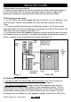
8.6 Prepare appliance fixing holes.
8.6.1 Screwing case to wall.
Recheck the position of the screw fixing holes
relative to the flue hole.
Drill the four fixing holes to a minimum depth of
42mm using a suitably sized masonry drill for the wall
plugs supplied.
Insert four plastic wall plugs supplied.
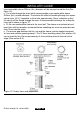
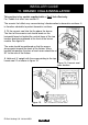
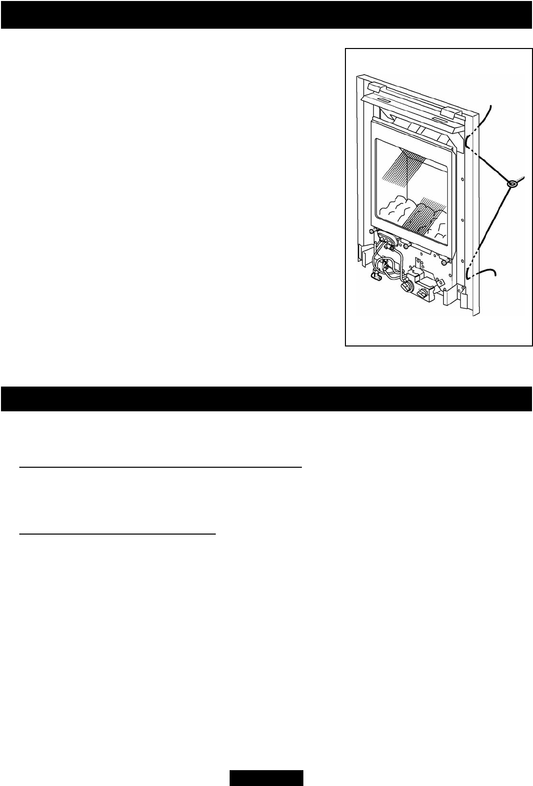
8.6.2 Using cable retention.
Thread the two tension cables through the
appliance case side holes as shown in figure 13.
Move the appliance towards the recess and mark on
the recess back wall the position for the two eyebolt
holes.
Remove the appliance and drill at the marked
positions using a suitably sized masonry drill for the
wall plugs supplied.
Insert the two fibre wall plugs supplied.
Fit the two eyebolts.
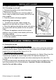
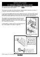
9. FLUE AND TERMINAL INSTALLATION
9.1 Cutting flue to size.
For outset appliances with surround or spacer
Measure the total wall thickness from the outside surface of the wall to the inside face
of the surround or spacer. Deduct 35mm from this measurement to obtain the correct
length of flue unit required (See figures 14 & 15).
For appliances inset in a recess
Measure the total finished wall thickness including plaster etc. Deduct 35mm from this
measurement to obtain the correct length of flue unit required (See figure 14).
Mark off the flue length on the outer (air) tube measuring from the end of the
terminal.
Insert the polystyrene ring between the inner and outer tubes to support them. Cut
both tubes squarely at the marked distance. Important: Remove all polystyrene
from the flue unit after cutting.
INSTALLER GUIDE
Figure 13. Cable retention
© Baxi Heating U.K. Limited 2009.
Page 24