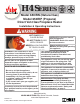
H4 SERIES Model 650IRN (Natural Gas) Model 650IRP (Propane) Direct Vent Gas Fireplace Heater Installation & Operating Instructions HOT GLASS WILL CAUSE BURNS. INSTALLER: Leave this manual with the appliance. DO NOT TOUCH GLASS CONSUMER: Retain this manual UNTIL COOLED. for future reference. NEVER ALLOW CHILDREN Please read this manual BEFORE installing and operating TO TOUCH GLASS. this appliance.
Thank You ... For purchasing a Valor by Miles Industries. Your new radiant gas heater is a technical appliance that must be installed by a qualified dealer. Each Valor fireplace is fully tested during the production process for your safety and comfort. Your unit has been professionally installed by: Dealer Name _______________________________________ Phone Number ______________________________________ Should you encounter an operational problem, call your dealer immediately.
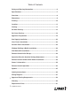
Table of Contents Safety and Warning Information ..............................................................4 Specifications ............................................................................................7 Overview.....................................................................................................8 Dimensions ................................................................................................9 Framing ..............................................................
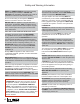
Safety and Warning Information READ and UNDERSTAND all instructions carefully before starting the installation. FAILURE TO FOLLOW these installation instructions may result in possible fire hazard and will void the warranty. Prior to the first firing of the fireplace, READ the Owner’s Information section of this manual. DO NOT USE this appliance if any part has been under water.
Safety and Warning Information Operating Your Fireplace for the First Time When operating your new fireplace for the first time, some vapors may be released due to the burning of curing compounds used in the manufacture of the appliance. They may cause a slight odor and could cause the flames to be the full height of the firebox, or even slightly higher, for the first few hours of operation. It is also possible that these vapors could set off any smoke detection alarms in the immediate vicinity.
Safety and Warning Information (c) MANUFACTURER REQUIREMENTS - GAS EQUIPMENT VENTING SYSTEM PROVIDED. When the manufacturer of Product Approved side wall horizontally vented gas equipment provides a venting system design or venting system components with the equipment, the instructions provided by the manufacturer for installation of the equipment and the venting system shall include: 1. Detailed instructions for the installation of the venting system design or the venting system components; and 2.
Specifications Approvals & codes Supply Gas These appliances are certified by ANSI Z21.88-2009/CSA 2.33-2009 American National Standard / CSA Standard for Vented Gas Fireplace Heaters for use in Canada and USA. These appliances are for installation directly venting through an outside wall or through the roof. Model 650IRN is for use with natural gas. Model 650IRP is for use with propane gas. Conversion between fuels may only be done using the approved conversion kits listed in the section Options.
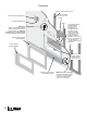
Overview Framing—See Framing section Remote Handset Wall Holder Fire On/Off Wall Switch Min. 3/4” (19 mm) Field convertible from top to rear outlet 650IR Wall Finish May be combustible material. NOTE: Finished wall surface, including tiles, etc., MUST be minimum 3/4” (19 mm) set back from the front face of the heater. Backing Plate required (sold separately) Mi n co . 1” mb (2 us 5 m tib m le ) f ma or ter ial Combustible framing allowed beneath fireplace.
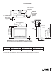
Dimensions MINIMUM 3/4” (19 mm) from finished wall surface to front of appliance Stand-off See table 36” (914 mm) min. 32-3/16” (817 mm) A Mantel See table 23-1/8” (587 mm) to rear vent center B 38-5/8” (981 mm) Stand-off 29-3/4” (756 mm) 30-3/4” (781 mm) Stand-off 26-3/4” (679 mm) 3” (76 mm) min.
Framing • A non-combustible hearth is not necessary in front of this appliance. • Note that the unit is installed at the framing stage and fixed to framing using support angles. See page 20. The wall finish is then installed over the support angles up to the front frame on the unit, on the sides and up to the stand-offs on the top.
Location Venting Vent Material Vent Penetration through Walls & Ceilings This unit is approved for installation using 4 by 6-5/8 inches diameter approved co-axial direct vent pipes and accessories listed on pages 38–39 of this guide. Follow the installation instructions supplied with the individual venting accessories.
Co-Axial Venting Typical Co-Axial Venting Components VERTICAL TERMINATION STORM COLLAR FLASHING ATTIC INSULATION SHIELD ATTIC FIRESTOP CEILING FIRESTOP 90˚ ELBOW PIPE LENGTH PIPE LENGTH HORIZONTAL 2-PIECE TERMINATION WALL THIMBLE PIPE LENGTH PIPE LENGTH 817VAK 817VAK 12
Co-Axial Venting Co-Axial Venting Rear Vent with No Vertical Rise The horizontal vent run cannot be extended by the use of any vent accessory pipes. * raise the appliance by at least 1/2” (13 mm) from surface of hearth or floor finish in front to allow for air gap below backing plate Rear vent—no vertical rise Vent pipe max. 15” (381 mm) after 45° elbow 26” (660 mm) max. vent length (14” (356 mm) max.
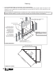
Co-Axial Venting Horizontal Vent Termination Location • The vent terminal must be located on an outside wall or through the roof. • This direct vent appliance is designed to operate when an undisturbed airflow hits the outside vent terminal from any direction. • The minimum clearances from this terminal that must be maintained when located on an outside wall are shown in figure below. Any reduction in these clearances could result in a disruption of the airflow or a safety hazard.
Co-Axial Venting Co-Axial Venting Configurations with Vertical Rise 4 x 90º ELBOWS MAXIMUM (or equivalent) V3 3” min. above top of horizontal pipe H2 1” min. all around vertical pipe 1” min. around bottom & sides of horizontal pipe V2 Min. 6” rise for top outlet H1 V1 Min. 12” rise 45° elbow directly on flue collar is allowed with min. 6” pipe between elbows Max.
Co-Axial Venting How to Read the Venting Chart The chart below applies to co-axial roof or wall termination in installations with vertical rise. See page 13 for installations with no vertical rise. 1. The total length of the vent pipe cannot exceed 40 feet (12.2 m). 2. The minimum vertical height with roof termination is 10 feet (3.05 m). 3. Any combination of rise and run can be used as long as they are within the allowable limits shown on the chart below. 4.
Co-Axial Venting Co-Axial Vertical Installations • Check the roof pitch to determine which roof flashing will be needed. See venting accessories list on pages 38–39 for allowable components. • The distance from the roof to the lowest terminal discharge opening (“H” in figure) depends on the roof pitch and must be in accordance with the manufacturer’s instructions supplied with the termination unit. Note: The venting system for these appliances is considered to be a Special Venting System.
Co-Linear Venting Co-Linear Vent Installations • The fireplace dimensions are shown in the Dimensions section of this manual. • Place the appliance (fitted with the co-linear adapter) near the fireplace opening but allow space for manipulating the chimney liners on to the appliance. • Drop the 3-inch diameter flexible liners into the chimney from outside. • Fit the liners to the co-linear adapter paying attention to inlet and exhaust and move the appliance to its proper position.
Appliance Preparation Window Removal 1. Turn the top two spring-loaded window bolts through 90 degrees to release the window from the firebox. 2. Remove the bottom two spring-loaded window bolts. 3. Carefully lift the window away. Keep the window and bolts in a safe place. Rear Vent Outlet Positioning If installing with top vent outlet, ignore this stage. If installing co-linear venting, see instructions supplied with the co-linear adapter. 1.
Appliance Preparation Stand-off and Support Angles Installation and Fitting The distance from the support angles to the front face of the heater case is adjustable to allow for a range of wall finish material thickness (e.g. tile, etc.). 1. Check the wall finish requirements with the homeowner. 2. Secure the side support angles from the inside of the appliance using two screws provided.
Appliance Preparation Air Restrictors Fitting No restrictors are required for appliances which only have a horizontal vent run. If installing an appliance which has a rear vent outlet connection and no vertical vent pipe rise, ignore this stage. A restrictor set, shown right, is supplied with each 650 engine unit. The restrictors cover part of the inlet air openings in the firebox rear wall behind the rear log support.
Gas Supply Installation • The gas supply pipe should enter the appliance case through the opening at the left side. The supply pipe should be connected to the appliance gas inlet pipe situated at the left side of the control valve. Supply line connection to the inlet pipe is 3/8 inch NPT (female). If the circulating fan is to be installed, be aware that the supply pipe run inside the case should be at the same height as the appliance inlet pipe in order to clear the fan.
Liner Panels Installation All liner panels can be installed as indicated below. Unpack the liners carefully to avoid scratching or damaging them. 1. Place the rear panel against the back of the firebox on the ledge of the rear log support. Make sure the bevel part is at the top. 4. Insert the top panel over the left side panel while holding the top panel forward up the slope. Rotate the right side of the top panel upwards and place it over the top of the right panel.
Ceramic Rocks Installation Unpack the ceramic rocks kit very carefully to avoid damaging the fragile material. Install the components as shown below. Please note that the position of the rocks and twigs (if used) is critical to ensure proper performance of the appliance. 1. Install the Front Support Platform in the firebox carefully sliding it down between the burner and the front bottom edge for the firebox while avoiding scraping the side ceramic panels. To p B ot to m 2.
Ceramic Rocks installation 4. The underside of each ceramic rock is identified by a number and a specific protruding positioning triangle. Install the six rocks from left to right starting with rock no. 1. Note: The ceramic base may need to be slightly adjusted side-to-side to allow stones to fit within the platform. Rock identification Triangular hole in ceramic base All Rocks Installed 5. Place the glass panel in its cavity formed by the Front Support and the Ceramic Platform. 6.
Window Refitting & Baffle Installation 1. Slide the window inside the appliance case and rest it on the firebox front bottom tabs. Refit the bottom two bolts. The bolts should be screwed in securely. 2. Refit the top two bolts securing by turning them through 90 degrees. 3. Hook the window baffle to the top of the window frame. Be careful not to hook it onto the firebox frame—see images below. 4.
Wall Switch Kit Installation 4. Take the switch wire and plug it into the receiver’s connection slot as indicated (the other slot should already be fitted with the valve’s wire harness connector). See diagrams below. IMPORTANT: The connection can only be done one way. Do not force it or damage the pins! 5. On the outside of the fireplace, run the switch wire into the outlet box. 6. Plug the wire into the switch plate and to the outlet box. 7.
Remote Control Initial Set-up The receiver and the handset of the remote control system must be initially synchronized before the first use. 1. Insert alkaline batteries in the remote control receiver and handset. The receiver is located left of the control valve under the burner module. 2. With a sharp object, press and hold the receiver’s reset button until you hear one short and one long beeps. Release the reset button after the second beep. 3.
Remote Control Handset Wall Holder Installation The remote control kit for this fireplace comes complete with a wall-mounted holder. This holder is not required in all installations but is provided as an optional feature for those customers who wish to mount the remote handset to the wall. To install the holder to the wall, find a convenient location and use the hardware provided with the kit. See the diagram on the right for required hardware and configurations.
Owner’s Information • • Use a soft damp cloth to apply the cleaner. Dry the glass with a soft, dry, preferably cotton cloth. Most paper towels and synthetic materials are abrasive to ceramic glass and should be avoided. Our dealers have had good results from the products listed below. We cannot, however, guarantee the results of these products.
Owner’s Information Batteries Fireplace Control Devices CAUTION DO NOT USE a screwdriver or other metallic object to remove the batteries from the receiver or the handset! This could cause a short circuit to the receiver. There are two ways to control your fireplace. 1. Thermostatic Remote Control 2. Wall Switch CAUTION To avoid short-circuit to the receiver, position the antenna so that it DOES NOT TOUCH the ignition wire. Low battery signal: see page 35.
Remote Control Operation NOTE: Before using the remote control system for the first time, the receiver and the handset must be synchronized. See the section Remote Control Initial Set-up on page 28 in this manual. Your fireplace remote control helps you get the comfort, convenience and aesthetics you want from your gas fireplace. The remote controls your fireplace in different ways.
Remote Control Operation Operation Modes STANDBY MODE—Ignited pilot only. MAN MAN MODE—Manual Mode. You can use this mode to adjust the flame height up or down. ☼TEMP TEMP MODE—Daytime Temperature Mode (appliance must be in Standby mode; pilot ignited): The room temperature is measured and compared to the set temperature. The flame height is then automatically adjusted to achieve the Daytime set temperature.
Remote Control Operation Temperature Use this setting when you come in and want to enjoy a set temperature. 1. Select either the ☼TEMP MODE or the ☽TEMP MODE by briefly pressing the SET button. 2. Hold the SET button until the TEMP display flashes. 3. Set the desired temperature with the or the buttons. Note: 4.5°C/40°F is the minimum temperature setting. 4. Press the OFF button or simply wait and the display will go to the temperature control mode.
Remote Control Operation Low Battery Indication Remote handset: BATT will appear on the display when the battery needs to be replaced. Replace with one 9 V alkaline battery. CAUTION DO NOT USE a screwdriver or other metallic object to remove the batteries from the battery box or the handset! This could cause a short circuit. Receiver: Three short ‘beeps’ will sound when the motor turns when the batteries need to be replaced. Replace with four 1.5 V alkaline batteries.
Lighting Instructions FOR YOUR SAFETY, READ BEFORE LIGHTING WARNING: If you do not follow these instructions exactly, a fire or explosion may result causing property damage, personal injury or loss of life. A. This appliance has a pilot which must be lighted by hand, remote control, or wall switch. Follow these instructions exactly. To save gas, turn the pilot off when not using the appliance for a prolonged period of time. B. BEFORE LIGHTING, smell all around the appliance area for gas.
Wiring Diagram Wall Switch Kit Connector Yellow Red GV60 Wiring Diagram 37
Approved Venting Components APPROVED DIRECT VENT SUPPLIERS FOR VALOR MODELS 530, 534, 535, 650, AND MF28 MILES INDUSTRIES — — — 551DVK 4DT-HC TM-4HT — — — Deluxe Co-axial — — TM-4DHT — — — High Wind Co-axial — — — SV4CHC — — Horizontal Vertical Termination Caps Vent Adapters / Couplers Aluminum Flexible Liner Adjustable Pipe Length 4” x 6-5/8” DV 45° Elbows DV 90° Elbows 38 SECURE VENT — 46DVA-HC ICC EXCEL DIRECT — Standard Co-axial SELKIRK Co-axial Kit, 26” long Venting P
Approved Venting Components ICC EXCEL DIRECT SECURE VENT 6” long 46DVA-06 4DT-06 TC-4DL6 SV4L6 Black 46DVA-06B 4DT-06(B) TC-4DL6B SV4LB6 Pipes 4” x 6 5/8” ( ID x OD ) 9” long Galvanized 46DVA-09 4DT-09 Black 46DVA-09B 4DT-09(B) 12” long Galvanized 46DVA-12 4DT-12 TC-4DL1 SV4L12 Black 46DVA-12B 4DT-12(B) TC-4DL1B SV4LB12 18” long Galvanized 46DVA-18 4DT-18 Black 46DVA-18B 4DT-18(B) 24” long Galvanized 46DVA-24 4DT-24 TC-4DL2 SV4L24 Black 46DVA-24B 4DT-24(B) TC-
WA TY N A RR M GR A O PR T LOR OR If you have a problem with this unit, please contact your dealer or supplier immediately. Under no circumstances should you attempt to service the unit in any way by yourself. The warranties in paragraphs 1 and 2 are provided only to the first purchaser/user of this unit, are not transferable and are subject to the conditions and limitations in paragraphs 3, 4 and 5. Please review the conditions and limitations carefully and strictly follow their requirements.
Replacement Parts Key Description Part no. Key Description Part no.
48 54 55 56 57 53 58 59 52 61 60 62 50 51 49 63 64 NG 11a LPG 41a 11b 13 42 12a 12b 41 65 47 14 15 17 18 16 19 20 21 22 23 46 27 43 45 44 28 24 29 1 30 3 2 31 25 32 26 34 35 33 40 3 39 38 36 37 4a 4 6 5 7 8 9 66 42
Thank You ... For purchasing a Valor by Miles Industries. Your new radiant gas heater is a technical appliance that must be installed by a qualified dealer. Please circle where appropriate - ask your installer or your dealer if in doubt. The information provided will be used for customer records only. Model: 650IR NG (natural gas) LPG (propane) Serial No: Front/Trim code/description (e.g.
Tape Shut Fold here Postage needed Miles Industries Ltd. 190 - 2255 Dollarton Highway North Vancouver, BC V7H 3B1 Canada Online Warranty registration at www.valorfireplaces.