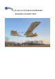
/3 SCALE SG-38 SCHULGLEITER KIT BUILDING INSTRUCTION
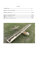
CATALOG INTRODUCTION----------------------------------------------------------------------------------------P3 PRODUCT LIST& KIT FEATURES -----------------------------------------------------------------P4 BUILDING INSTRUCTION---------------------------------------------------------------------------P6-P41 1) FUSELAGE FRAME ASSEMBLY---------------------------------------------------------------P6-P19 2) WING CONSTRUCTION-------------------------------------------------------------------------P19-29 3) TAIL-
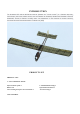
INTRODUCTION THE SCHNEIDER DFS 108-14 SG-38 SCHULGLEITER (GERMAN FOR '"SCHOOL GLIDER"') IS A GERMAN HIGH-WING, CABLE-BRACED, SINGLE-SEAT PRIMARY GLIDER THAT WAS DESIGNED BY SCHNEIDER, REHBERG AND HOFMANN AT EDMUND SCHNEIDER'S FACTORY AT GRUNAU IN 1938, HENCE THE DESIGNATION.
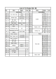
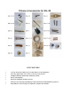
KIT FEATURES 1/3 Scale detail and scheme-based on DFS 108-14 SG-38 Schulgleiter. Extremely lightweight, state-of-the-art all-wood construction Complete hardware pack.Comes with air tow hook. Power system option. Full-scale simulation metallic structure. Extensive clear drawings and full-page colour instructions with hundreds of pictures . Only adhesives and coverings are required to complete the airframe.
GERNERAL INFORMATION BE SURE TO READ THE SAFETY INSTRUCTIONS CAREFULLY BEFORE OPERATING YOUR MODEL. • Always follow the procedures and settings recommended in the instructions. • If you are using remote-controlled model aircraft, helicopters, cars or ships for the first time, we recommend that you ask an experienced model pilot for help. • Remote-controlled models are not toys in the usual sense and may only be used and operated by young people under 14 years of age under the supervision of adults.
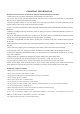
BUILDING INSTRUCTION 1 FUSELAGE FRAME ASSEMBLY 1) Assemble the rear part of the fuselage according to the drawing. 2) The joints are strengthened with pine blocks.
3) Stick the reinforcement plywood with the corresponding number on both sides of the strips. 4) Stick 5X16MM pine strips on the tail. 5) Stick 5X16MM pine strips up and down the fuselage.
6) Saw off excess wood strips. 7) Stick 5X16MM pine strips in the middle. 8) Assemble fuselage lateral plates.
9)Stick 8X25MM pine strips on the fuselage lateral plate and reserve the position for servos installation. 10)Stick the other lateral plate. 11) Joint 12X16MM pine strips according to the drawing, and strengthen the top position with pine. \
12) Stick the pine reinforcement block. 13) Stick the plywood. 14) Fill pine block. 15) Make 8X16MM pine strips as the the one in the picture.
16) Stick the pine wood and the polywood No.37 according to the drawing style. 17) Combine the 3 parts.
18) Combine fuselage rear, reinforced with pine blocks. 19) Stick lateral strips. 20) Assemble and stick the two pcs of A3 polywood sheets and build the cockpit according to the position in the drawing.
21) The tow hook is needed to be bent, assembled with 3MM screws and mounted to the fuselage. 22) The tow hook is needed to be bent, assembled with 3MM screws and mounted to the fuselage. 23) Pine strips for cabin construction.
24) Stick bottom cover. 25) Stick the balsa sheets and polish to be radian, so that the cover has a larger bonding area. 26) Stick both sides of the cover and the upper panel.
27) Stick pine strips at the rear of the cockpit. 28) Stick the cover for rear cockpit.
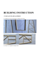
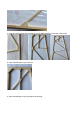
29) Make the seat. 30) Soak 4X25MM pine strips with hot water, so that it is easier to bend, use glue to stick and shape.
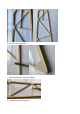
31) Install prefabricated metal pieces. 32) The hole is drilled on the front panel for tow hook wires. 33) Install bracing wires tension components.
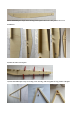
2 WINGS ASSEMBLY 1) Assemble the two polywood sheets and stick 8X6MM pine strips. The left and right girders are not the same. Note that there are directions marked on the polywood. 2) Stick the reinforcing board in front and middle of girder.
3) Punch holes in the girder using metal parts as templates. 4) Insert the ribs into the main girder according to the drawing numbers and keep the ribs vertical.
5) Fix aileron servos mounting plate. 6) Stick the leading edge polywood. 7) Stick 5X10MM pine strips on the back edge.
8) Stick aileron trailing edge polywood.
10)Install the metal connectors. 11) Stick rib B1. 12) Stick the inner bracket of the wing. 13) Stick the servos cover plate.
14) Stick balsa wood onto the front wing girder and smooth it. 15) Wing tip sticked balsa wood can be increased the pasting area. 16) Stick the wing cover.
17) Stick the wing root and tip cover.
18) Fill the joint with balsa wood. 19) Paste 8MM balsa sticks on the leading edge of the wing and polish it.
20) Stick balsa wood at aileron connecting rod exit . 21) Assemble ailerons according to the rib numbers and paste reinforcement plates.
22) The position of the horn is strengthened by sticking pine block. 23) Stick 8MM balsa wood on the front end of the aileron and polished into triangles.
3 THE TAIL ASSEMBLY 1) Stick parts according to drawings.
2) Make the leading edge with balsa.
3) The position of horns should be reinforced with pine blocks.
4) Elevator. 5) Stick the horizontal tail fin according to the drawing position.
6) Stick the pine stiffener. 7) Wing tip.
8) Stick 1MM polywood. 9) Leading edge--- 8MM balsa stick. 10) Polish the leading edge balsa. 11) Stick the pine reinforcement block.
4 OVERALL ASSEMBLY DETAILS 1) Secure the horizontal tail joint with M3 screws. 2) Assemble the tail fins on the fuselage, mark the position where need to drill a 3MM hole, keeping the perpendicularity of the holes.
3) Install metal fittings in the middle of the fuselage. 4) Install pulley with M3 screws. 5) Install landing skid connections with tapping screws.
6) Install skid retaining mount. 7) Install skid to fuselage. 8) Make tail support rods with 8X6MM pine strips. 9) Connection of main wing.
10) Connection of the middle of the fuselage.
11) Mounting for elevator pulleys. 12) Installation of the bracing wires for the fuselage and tail. 13) Install motor mount to the fuselage .
4 FINISHED