
Manual


PAGE 3
SECTION 2 INSTALLATION
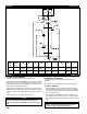
FIGURE 3 RECOMMENDED INSTALLATION DRAWING
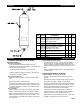
2.2-D MANUAL DRAIN VALVE
The drain port is a 1/2" NPT tapped hole in the
center of the vessel bottom head.
Shipped separately with the dryer is (1) 1/2" NPT
close nipple and (1) 1/2" NPT brass ball valve.
Install the nipple and valve into the drain port.
The drain of the dryer can be remotely piped away
from the dryer. Make sure that the line is vented to
atmospheric pressure. Any remote drain piping
should be of the same size and on the same level or
lower than the drain valve.
IMPORTANT
The drain solution may contain lubricants.
Comply with all applicable regulations
concerning the disposal of these chemicals
CAUTION
DO NOT CONNECT THE DRAIN TO A
PRESSURIZED LINE.
NOTE:
ITEMS CALLED OUT IN THIS DRAWING
ARE NOT SUPPLIED WITH THE DRYER.
REFERENCE FIGURES 1 & 4 FOR ITEMS
INCLUDED WITH DRYER.
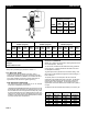
2.1-G OPERATING PRESSURE
More air can be processed through the dryer at higher pressures.
Locate the dryer at the highest practical pressure, but do not exceed
the maximum rated working pressure of the dryer. Refer to FIGURE
2 located on page 3 for the maximum working pressure for your dryer.
2.2 PIPING AND ANCILLARY EQUIPMENT
Locate the dryer in the proper location as explained in the previous
section.
If the dryer is being installed in an existing piping system, make sure that
the pipe is free of scale and rust.
The dryer will be supported by the piping system. Adequate pipe
supports must be used to prevent damage to the pipeline and dryer.
2.2-A INLET AND BYPASS PIPING
Using Figure 3 as a reference, make the necessary piping connections
into the dryer.
Inlet and outlet isolation valves should be installed on the dryer.
These valves will aid in the start up and shutdown of the dryer. The
inlet isolation valve should be mounted before the pressure relief
valve. The outlet isolation valve should be installed on the dryer outlet.
A bypass valve and piping should also be installed. This will allow the
dryer to be taken off stream without interrupting the air system.
2.2-B OPTIONAL PRESSURE RELIEF VALVE (p/n 14-2213)
A pressure relief valve should be installed to conform to OSHA safety
standards. Refer to OSHA Standard Section 1910.169, paragraph
b, subparagraph 3 and any other federal, state or local codes
concerning pressure vessels.
2.2-C OPTIONAL PRESSURE GAUGE (p/n 29-0150)
An optional pressure gauge is available for this dryer.
CAUTION
THE DRAIN SOLUTION WILL BE DISCHARGED UNDER LINE
PRESSURE. POINTING THE DRAIN IN THE DIRECTION OF
PEOPLE AND EQUIPMENT MAY RESULT IN INJURY AND
DAMAGE.
DO NOT INSTALL A FLOAT TYPE (OTHER THAN THE PDV-500)
OR SOLENOID TYPE DRAIN ON THE DRYER. THE DRAIN
SOLUTION WILL CAUSE THESE TYPES OF DRAINS TO FAIL,
THUS RESULTING IN FLOODING OF THE DRYER.
2.2-E OPTIONAL AUTOMATIC DRAIN VALVE (p/n 39-2211121)
The MDV-400I drain valve is recommended. Use model PDV-500 (PN
39-0283) for pneumatic applications. Contact your local VAN AIR
representative to order.
Complete the automatic drain valve installation as outlined in the
instructions supplied with the drain. The drain line can be remotely
piped, follow the precautions as outlined previously.
2.2-F AFTERFILTER
The installation of an afterfilter prevents any accidental flow of materials
from the dryer into the downstream piping.
The afterfilter can be installed before or after the outlet isolation valve.
If the afterfilter is installed before the isolation valve, the filter can be
isolated from the air system when the dryer is isolated for maintenance.
Contact your local VAN AIR representative to order.
DRYER FILTER
D-4 F200-15-1/4-B
D-8 F200-55-1/2-B
2.2-G DESICCANT INSTALLATION
IMPORTANT
This dryer was shipped WITHOUT the desiccant installed. The
desiccant MUST BE INSTALLED before using the dryer
The procedures for filling the dryer with desiccant are outlined in Section
4.4 of this manual.