
Installation manual


16
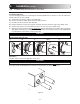
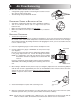
5- Make sure the instruction pull-out is in the occupant’s
language. If not, turn it to the other side.
6- Reinstall the cover plate and the button.
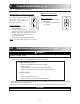
7- Connect the wires to their corresponding position inside the
electrical compartment.
Make sure the connections of the unit and of the wall control
correspond exactly.
8- Connect the optional controls.
9- Do the appropriate connection to the furnace (if applicable) by referring to Section 6.3.
10- NOTE: If you are in a cold region, set up “extended defrost” by removing jumper JU1F on the main
circuit board inside the electrical compartment (see Section 7).
11- Plug in the unit and do the “overall verification” of the system as described in Section 9.
6.
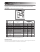
Maximum Main Control (cont’d)
F
F
I
OC
OL
YR
G
B
VE0084
VC0061
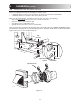
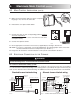
6.2 MAIN CONTROL INSTALLATION (CONT’D)
W R G
Y
W
R
G
C
Y
9
8
7
6
5
4
3
2
1
UNIT CONTROL CONNECTOR
THERMOSTAT
TERMINALS
FOUR
WIRES
I OC OL Y R G BF F
J3
TWO WIRES
heating only
FURNACE
24-VOLT
TERMINAL BLOCK
TWO WIRES
COOLING SYSTEM
VE0010A
Standard furnace interlock wiring
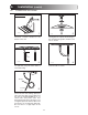
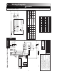
6.3 ELECTRICAL CONNECTION TO THE FURNACE
WRGY
W
R
Y
R
G
Y
C
J1
1
2
4
5
6
8
93
*FURNACE INTERLOCK
RELAY
NC NO
7
COM
7
THERMOSTAT
TERMINAL
Unit Control Module
4 WIRES
2 WIRES
(heating only)
wiring
nuts
FURNACE
24-VOLT
TERMINAL BLOCK
2 WIRES
COOLING SYSTE
M
GRAY BROWN
RED
GREEN
BLUE
9-PIN AMP PLUG
*FURNACE INTERLOCK RELAY, PART # 12658
VE0009A
Alternate furnace interlock wiring
For a furnace connected to cooling system:
On some older thermostats, energizing the “R” and “G” terminals at the furnace has the effect of energizing
“Y” at the thermostat and thereby turning on the cooling system. If you identify this type of thermostat, you
must use the “alternate furnace interlock wiring”. An additional control relay will then have to be installed.
WARNING
Never connect a 120-volt AC circuit to the terminals of the furnace interlock (standard wiring). Only
use the low voltage class 2 circuit of the furnace blower control.
!