
Installation manual


19
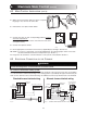
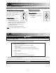
9.1 MAIN CONTROL
This procedure allows the installer to verify that all modes of operation are fully functional.
During the verification of the main control, make sure that all remote controls are inactive.
9.
Overall Verification
VC0092
Maximum
M a x i m u m
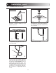
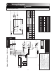
MAXIMUM (14 different control scenarios to be tested)
Results expected
Set air supply Set dehumidistat Fan Exchange Max. speed
control to dial to speed indicator indicator
(A)(B)
1 OFF maximum counterclockwise off *off off
2 OFF maximum clockwise off *off off
3 MIN. (green light) maximum counterclockwise low on off
4 MIN. (green light) maximum clockwise high on on
5 MIN. (red light) maximum counterclockwise low *off off
6 MIN. (red light) maximum clockwise high on on
7 MAX. (green light) maximum counterclockwise high on off
8 MAX. (green light) maximum clockwise high on on
9 MAX. (red light) maximum counterclockwise high *off off
10 MAX. (red light) maximum clockwise high on on
11 INTERMITTENT
maximum counterclockwise
off/40 min. *off/40 min. off
(green light) low/20 min. on/20 min. off
12 INTERMITTENT
maximum counterclockwise high on on
(green light)
13 INTERMITTENT
maximum counterclockwise
low/20 min. on/20 min. off
(red light) high/40 min. *off/40 min. off
14 INTERMITTENT
maximum counterclockwise high on on
(red light)
*The dampers are closed when the exchange indicator is off.
A
B
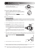
PERMANENT MEMORY
This electronic control has a default memory feature in the event of a power outage. Even the date of the
last service reminder is maintained as a convenience to the homeowner.