Vanguard 3400 Access Services Gateway Series Installation Manual
Notice ©Copyright © 200X-2007 Vanguard Networks Solutions, LLC. All rights reserved. 25 Forbes Boulevard Foxboro, Massachusetts 02035 +1 (508) 964-6200 All rights reserved Printed in U.S.A. Restricted Rights Notification for U.S. Government Users The software (including firmware) addressed in this manual is a "commercial item" as that term is defined in 48 C.F.R. 2.101, consisting of "commercial computer software" and "commercial computer software documentation" as such terms are used in 48 C.F.R. 12.212.
Notice (continued) Proprietary Material Information and software in this document are proprietary to Vanguard Networks (or its Suppliers) and without the express prior permission of an officer of Vanguard Networks may not be copied, reproduced, disclosed to others, published, or used, in whole or in part, for any purpose other than that for which it is being made available. Use of software described in this document is subject to the terms and conditions of the Software License Agreement.
If this equipment causes harm to the telephone network, the telephone company will notify you in advance that temporary discontinuance of service may be required. But if advance notice isn't practical, the telephone company will notify the customer as soon as possible. Also, you will be advised of your right to file a complaint with the FCC if you believe it is necessary.
Contents About this Manual Overview ...................................................................................................... vii Chapter 1. About the Vanguard 3400 Series Overview ...................................................................................................... Features ......................................................................................................... Applications ....................................................................................
Contents (continued) Appendix A. Specifications Overview ...................................................................................................... A-1 Appendix B. Software License and Regulatory Information Overview ...................................................................................................... B-1 FCC Part 68 and Telephone Company Procedures and Requirements for DSU and T1 Interfaces .............................................................................
About This Manual Overview Introduction This installation manual describes features, hardware, specifications, and applications for the Vanguard 3400 Series. Note For information on operating system software and configuration, see the Vanguard Basic Configuration Manual (Part Number T0113). Audience This manual is intended for people who install and operate the Vanguard 3400 Series products.
This Page Intentionally Left Blank
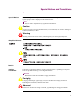
Special Notices and Translations Special Notices The following notices emphasize certain information in the guide. Each serves a special purpose and is displayed in the format shown: Note Note is used to emphasize any significant information. Caution Caution provides you with information that, if not followed, can result in damage to software, hardware, or data. Warning Warning is the most serious notice, indicating that you can be physically hurt.
Dutch Bijzondere vermeldingen De volgende vermeldingen besteden extra aandacht aan bepaalde informatie in de handleiding. Elke vermelding heeft een eigen nut en wordt in de volgende opmaak weergegeven: Opmerking Een opmerking wordt gebruikt om belangrijke informatie te benadrukken. Let op Dit kopje geeft aan dat u de beschreven instructies moet volgen om schade aan de software, hardware of gegevens te vermijden. Waarschuwing Een waarschuwing is de belangrijkste vermelding.
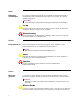
Avertissement Un avertissement constitue le message le plus sérieux, indiquant que vous pouvez subir des blessures corporelles. German Besondere Hinweise Durch die folgenden Hinweise werden bestimmte Informationen in diesem Handbuch hervorgehoben. Jeder Hinweis dient einem bestimmten Zweck und wird im dargestellten Format angezeigt: Wichtig WICHTIG wird zur Betonung signifikanter Angaben zu Vorgehensweisen verwendet.
Japanese Korean Norwegian Spesielle merknader Merknadstypene nedenfor representerer en bestemt type informasjon i håndboken. Hver merknadstype har en spesiell hensikt og vises på følgende format: Merk Merk brukes for å fremheve viktig informasjon. Forsiktig Forsiktig gir deg informasjon om situasjoner som kan føre til skade på programvare, datamaskin eller data dersom den blir fulgt. Advarsel Advarsel er den mest alvorlige merknaden og indikerer at du kan bli fysisk skadet.
Portuguese/ Portugal Avisos Especiais Os avisos que se seguem realçam certas informações neste guia. Cada um deles serve um objectivo especial e é visualizado no formato apresentado: Nota Nota é utilizado para realçar qualquer informação importante. Atenção Atenção faculta-lhe informações que, se não forem cumpridas, poderão provocar danos no software, hardware ou nos dados. Cuidado Cuidado constitui o aviso mais grave, o qual indica que poderá ficar fisicamente ferido.
Varning Varning är den mest allvarliga beteckningen och den indikerar att du kan skadas fysiskt.
Customer Information Customer Questions Customers who have questions about Vanguard Networks products or services should contact your Vanguard Networks representative or visit this website for product, sales, support, documentation, or training information: http://www.vanguardnetworks.com/ Comments About This Manual Customer Information To help us improve our product documentation, please complete the comment card included with this manual and return it by fax to (508) 543-0237.
This Page Intentionally Left Blank
Customer Response Card Vanguard Networks would like your help in improving its product documentation. Please complete and return this card by fax to (508) 543-0237; Attention: Product Documentaton, to provide your feedback. To discuss comments with a member of the documentation group, provide telephone information at the bottom of this page. Thank you for your help.
This Page Intentionally Left Blank
Chapter 1 About the Vanguard 3400 Series Overview Description The Vanguard 3400 Access Services Gateway Series is a single platform that can support any application to any service, providing wide area network (WAN) access for service provider and enterprise customers. Figure 1-1. Vanguard 3400 Series For a detailed description of the Vanguard 3400 Series and its features, refer to the “Features” section on page 1-2.
Features Features Introduction This section summarizes the features available with your Vanguard 3410 and Vanguard 3460. For descriptions of the software running on your Vanguard 3410/ 3460, refer to the appropriate protocol document. This table lists the hardware features of the Vanguard 3400 Series: Hardware Features Product Target Memory OnBoard Flash Compact Flash Form Factor Daughter Card Slots Mini PCI Card Slots Ethernet Ports (Total) 10/100BT Serial Ports MB Serial Ports CTP DC Serial Ports V.
Features Hardware Features (continued) Product VG 3410 Target Small Branch FSP Data Only Power (DC) N Redundant Power N VG 3460 Small Branch IPT Gateway N N For additional information about the rear panel ports and the daughtercards, refer to appropriate section in Chapter 2, Hardware Description. For information about the physical specifications of the Vanguard 3400 Series, refer to Appendix A, Specifications.
Features Vanguard 3400 Series Daughtercard Matrix (continued) Description V.90 (Modem) Product Code Assembly Number 3410 DC Site --- 1152-10003 3460 DC Site 1 Yes DC Site 2 Yes Note If a table entry contains the value "Yes", the daughtercard type will be supported in the DC Site for that platform. If a table entry contains the entry " --- ", the daughtercard type will not be supported in that DC Site of that platform. Software Support The Vanguard 3410/60 requires Release 7.0.
Applications Applications Introduction This section illustrates some typical applications of the Vanguard 3410/60. Ethernet Vanguard 3410 Multiple Devices BSC Vanguard 6841 MPLS/FR Corporate Data Center FT1 Vanguard 3410 xDSL Modem Back Up Figure 1-2.
Applications Serial Vanguard 3410 IPSec Vanguard 6841 Multiple Devices IPSec MPLS/FR Corporate Data Center IPSec FT1 Vanguard 3410 xDSL Modem Back Up Figure 1-3.
Applications Soft Switch 6800 Series WAN (IP/MPLS) PRI Main Office PSTN FXO 3460ASG Analog Phone IP Telephone Laptop Fax Small/Medium Branch Office Figure 1-4.
Applications 7300 Series IPSec WAN PRI Data Center IPSec PSTN SIP IPPBX FXO 3460ASG Analog Phone IP Telephone Laptop Fax Small/Medium Branch Office Figure 1-5.
Chapter 2 Hardware Description Overview Introduction This chapter describes the Vanguard 3400 Series.
Enclosure Enclosure Introduction This section describes the components of the Vanguard 3400 Series enclosure. Enclosure The Vanguard 3400 Series models are standalone units with an external 110/220 VAC power supply that can be used either on a desktop or installed on a rack shelf. The enclosures contain a motherboard, (optional) daughtercards, and optional mini PCI modules. Front Panel The front panel of the Vanguard 3400 Series (see Figure 2-1) has two LEDs that provide node status.
Enclosure DC Site 1 Ports 7-9 3410 5V DC RS-232 Serial Power (Sync/Async) Input Port 1 3460 CTP Port 4 DC Site 1 (Ports 7-9, 51-54) 5V DC Multi-Function CTP Power Port 4 Serial Input Port 1 Routed Ethernet Ports Ports 23, 24 DC Site 2 (Ports 10-12, 61-64) Routed Ethernet Ports Ports 23, 24 Figure 2-2. Vanguard 3400 Series Rear Panels Note For information about cabling, refer to the “Cabling Your Vanguard 3400 Series” section in Chapter 3.
Motherboard Motherboard General Description The Vanguard 3400 Series motherboard contains 16 MB flash and 64 MB of SDRAM memory. It uses the MPC8270 CPU operated in single MPC 8270 mode. Additionally, the motherboard supports the following: • One or two daughtercards, depending on which model you have (see daughtercard matrix on page 2-6 for model-specific support) • One Serial Port, depending on which model you have • Up to two 10/100 Base T auto-sensing Ethernet ports.
Motherboard Future Expansion Connection for Upgradeablity Daughtercard Slot 1 Serial Number Label Encryption Module Battery Daughtercard Slot 2 Fan Figure 2-5. Vanguard 3460 Series Motherboard Accessing the Motherboard To access the motherboard components you must remove the motherboard from the enclosure. • For information about removing and installing the motherboard refer to the “Accessing the Motherboard” section in Chapter 3.
Vanguard Networks Daughtercards Vanguard Networks Daughtercards Supported Daughtercards The table below identifies the daughtercards supported by each 3400 series model, as well as any daughtercard slot restrictions that may apply. Vanguard 3410 Daughtercard Matrix Description 2P-SDC (2-Port Serial) 56K DSU Dual E&M Dual FXS FT1 - 120 Ohm FE1 - 120 Ohm FE1 - 75 Ohm FXS/FXO G.SHDSL Quad FXO Quad FXS ISDN BRI S/T ISDN BRI S/T ISDN BRI-U V.11 DCE (Serial) V.24 DCE (Serial) V.35 DCE (Serial) V.
Vanguard Networks Daughtercards Daughtercard Compatibility Older Vanguard Networks Daughtercards do not fit into the Vanguard 3400 Series. You can only use the newer daughtercards which are identified by a dimple as shown in Figure 2-5. If the dimple is not present, do not attempt to use the Daughtercard in the Vanguard 3400 Series. Also, when installing a Vanguard Networks Daughtercard into a 3400 Series, you must use the shorter two-sided header.
Vanguard Networks Daughtercards FT1/FE1 Daughtercards The FT1/FE1 Daughtercards allow a Vanguard 3410 to transfer data over a T1 or E1 network. The daughtercards support full and fractional, channelized, T1 or E1, and PRI ISDN speeds. • The E1 Daughtercard provides line rates 2.048 Mbps and data rates of n x 64 kbps (where n is 1 to 31) per channel. • The T1 Daughtercard provides line rates 1.544 Mbps and data rates of n x 64 kbps (where n is 1 to 24) per channel.
Vanguard Networks Daughtercards 4-Port Voice FXO Daughtercard The Vanguard Quad FXO Daughter Card is supported on the Vanguard 3460/3480. The 4-Port Voice FXO Daughtercard has four RJ11 connectors for four FXO Ports. Figure 2-11 shows the 4-Port Voice FXO Daughtercard connectors as they appear on the back panel. FXO-1 FXO-2 FXO-3 FXO-4 Figure 2-11. FXO Daughtercard V.90 Modem Daughtercard The V.
Vanguard Networks Daughtercards This Page Intentionally Left Blank 2-10 Hardware Description
Chapter 3 Installation and Replacement Overview Introduction This chapter provides instructions for the following tasks: • • • • Installation and Replacement Checking Your Shipment Contents. Installing the Vanguard 3400 Series. Cabling the Vanguard 3400 Series. Modifying Your Vanguard 3400 Series.
Checking Your Shipment Contents Checking Your Shipment Contents List of Contents Before you install the Vanguard 3400 Series, make sure your shipment contents are complete. The Vanguard 3400 Series is packaged in shock-absorbent packing material. Inside your shipping carton, you should find the contents shown in Figure 3-1. Vanguard 3400 Series Power Supply Vanguard 3400 Series Vanguard 3400 Series Shipping Contents • Vanguard 3400 Series enclosure • Power Supply Power Cord (Optional) Figure 3-1.
Installing The Vanguard 3400 Series Installing The Vanguard 3400 Series Introduction This section explains how to install the Vanguard 3400 Series. It consists of these sections: • Selecting and preparing the installation site. • Installation. • Thermal considerations. • Cabling. After the Vanguard 3400 Series is installed and cabled, go to Chapter 4, Powering Up Your Vanguard 3400 Series for instructions for powering-up the unit.
Installing The Vanguard 3400 Series Installation How to Choose a Site Before you install the Vanguard 3400 Series, select a site for the device. Choose a site that is within an appropriate distance of a power source. Depending on your application, and the country in which the Vanguard 3400 Series is to operate, the power source must be a grounded 110 to 220 Vac outlet.
Installing The Vanguard 3400 Series Installation Complete these steps to install the unit: Step Action 1 Unpack the Vanguard 3400 Series, and inspect the unit to ensure you have all the components. 2 Install any daughtercards that you need to add to the unit, as necessary. 3 Be sure that the four rubber feet are on the bottom of the enclosure. 4 Attach the power cord and cables to the rear panel. Refer to the “Cabling Your Vanguard 3400 Series” section on page 3-7 for cabling information.
Installing The Vanguard 3400 Series Thermal Considerations Introduction This section explains some of the heat and temperature factors that can affect your Vanguard 3400 Series. Temperature After the unit is running, check the ambient air temperature. Make sure it does not exceed the operating temperature limits specified in Appendix A.
Installing The Vanguard 3400 Series Cabling Your Vanguard 3400 Series Introduction This section provides information to help you cable your Vanguard 3400 Series. Caution Before connecting cables to the motherboard or daughtercard ports, be sure that the screws holding the motherboard in place are installed. Otherwise, the motherboard could loosen under the weight of the cables and cause damage to the equipment. Also use proper cable strain relief to prevent damage due to excessive cable weight.
Installing The Vanguard 3400 Series There are up to twelve physical ports (8 voice, 2 LAN, 1 Serial, and 1 CTP) on the Vanguard 3400 Series rear panel. Some physical port numbers may vary from model to model. Rear Panel Ports Port 1 Port 1 of the 3410 is a RS232 Serial Interface. Port 1 of the 3460 is a Universal (V.24/RS232, V.35/V.36, or V.11/X.21) Serial Interface.. . 3410 Motherboard Port 1 Cabling Interface Type DCE-DTE Crossover Cable Cable Motherboard Port 1 V.
Installing The Vanguard 3400 Series 3460 Motherboard Port 1 and 2-Port Serial Data Card Interface (continued) Cabling Interface Type V.24/RS232 DTE Y-Cable (one per 2-PSDC) Cable Adapter (one per port) 62026-01 DB50M- N/A two DB25Fs DCE-DTE crossover Cable (one per port) Adapter Cable (one per port) 80110 3' DB25M-DB25M or 80109 15' DB25M-DB25M N/A V.35 or V.36 DCE 62026-01 DB50M-two DB25Fs 1152-10021 DB25M-DB25F N/A 92104 7' DB25M-M34F V.35 or V.
Installing The Vanguard 3400 Series This table describes the DB25 connector pinouts for port 1: DB25 V.
Installing The Vanguard 3400 Series This table shows the pinouts for RJ-45 connectors for port 4: Pin Number Port 4 (CTP) Signal DCE 1 RTS Input 2 DTR Input 3 RXD Output 4 DCD Output 5 GND ------- 6 TXD Input 7 DSR Output 8 CTS Output Note Use Port 4 only with low speed asynchronous protocols. Running asynchronous protocols at speeds greater than 19.2 kbps may degrade node performance.
Modifying Your Vanguard 3400 Series Modifying Your Vanguard 3400 Series You can modify your Vanguard 3400 Series by adding or replacing daughtercards or mini-PCI modules. This section explains how to make these modifications. Introduction Installing a Daughtercard You can install one Vanguard Networks Daughtercards in the Vanguard 3410 and two Vanguard Networks Daughtercards in the 3460.
Modifying Your Vanguard 3400 Series Accessing the Motherboard Introduction This section explains how to access the motherboard for the Vanguard 3400 Series. It also identifies the location of the key motherboard components. Before replacing modules, batteries, or daughtercards, you must access the Vanguard 3400 Series motherboard. Instructions for the Figure 3-7 shows how to remove and install the Vanguard 3400 Series motherboard. Figure 3-8 shows the location of the components on the motherboard.
Modifying Your Vanguard 3400 Series Caution When handling any components or cards, use ESD protection. Removing the Motherboard 1 Power down the unit and remove the cables and power cord. 2 Remove the two screws on either side of the motherboard rear panel. 3 Pull motherboard out of chassis by grabbing the bottom edge of rear panel and carefully sliding it out of chassis. 4 Place the motherboard on a clean flat surface.
Modifying Your Vanguard 3400 Series Motherboard Components Figure 3-8 shows the components on a Vanguard 3410 Series motherboard and Figure 3-9 shows the components on a Vanguard 3460 Series motherboard. Future Expansion Connection for Upgradeablity Daughtercard Slot 1 Encryption Module Serial Number Label Battery Figure 3-8.
Modifying Your Vanguard 3400 Series Future Expansion Connection for Upgradeablity Daughtercard Slot 1 Serial Number Label Encryption Module Battery Daughtercard Slot 2 Fan Figure 3-9.
Modifying Your Vanguard 3400 Series Installing and Removing the Encryption PCI Mezzanine Card Introduction The Encryption PCI Mezzanine card is an option and may have been installed on the motherboard at the factory. If not, you can install or replace the card. This section explains how to: • Add and remove Encryption PCI Mezzanine Card. For instructions for removing the motherboard, refer to the “Accessing the Motherboard” section on page 3-13.
Modifying Your Vanguard 3400 Series Release Lever Inserting Encryption PCI Mezzanine Card Removing Encryption PCI Mezzanine Card Adding Encryption PCI Mezzanine Card 1 Insert the module into the connector at an angle as shown. 2 Push down on the module so that it is parallel to the motherboard and the release levers lock it into place. Removing Encryption PCI Mezzanine Card 1 Pull outward on the release levers at the side of the card, to allow the module to be removed from the connector.
Modifying Your Vanguard 3400 Series Installing/Removing the Lithium Battery Introduction Vanguard 3400 Series uses a lithium battery on the motherboard to maintain the node’s realtime clock. The battery is not used to store the configuration memory. This section explains how to replace the battery. Warning Only qualified service personnel should perform the procedure described in this section.
Modifying Your Vanguard 3400 Series Routine Battery Replacement The lithium battery should be replaced every two years. Follow the instructions in Figure 3-11 to replace the battery. Before Removing/ Installing the Battery Before you remove or install the battery, you must access the Vanguard 3400 Series motherboard as described in the “Accessing the Motherboard” section on page 3-13. Removing/ Installing the Battery Figure 3-11 shows how to install and replace the battery.
Chapter 4 Powering Up Your Vanguard 3400 Series Overview Introduction This chapter explains how to: • Power up your Vanguard 3400 Series. • Ensure that the unit powered up correctly and is up and running by reading the front panel LEDs. • Load the Vanguard 3400 Series software.
Power Up Procedure Power Up Procedure Introduction This section explains how to power up the Vanguard 3400 Series. Procedure Follow these steps to power up your Vanguard 3400 Series. Step Action 1 Ensure that all the cards are fully inserted and secure. 2 Ensure that the AC power cord is plugged in. 3 Ensure the front panel power LED is on. To power down the Vanguard 3400 Series, unplug the power supply AC power cord from the power receptacle.
Loading the Software Loading the Software Introduction This section briefly describes how to load the software into your Vanguard 3400 Series. Note After the software has been loaded, refer to the appropriate user document to configure and use the different software options. Operating Software The operating software is compressed in FLASH and loaded into SDRAM for execution. There are a variety of operating software feature sets available for the Vanguard 3400 Series.
Loading the Software This Page Intentionally Left Blank 4-4 Powering Up Your Vanguard 3400 Series
Appendix A Specifications Overview Introduction This appendix describes the physical and electrical specifications for the Vanguard 3400 Series. Dimensions Figure A-1 shows the exterior dimensions of the Vanguard 3400 Series. Width: 8.4 in. (21.3 cm) Height: 2.6 in. (6.6 cm) Length: 11.6 in. (29.5 cm) Figure A-1. Vanguard 3400 Series Exterior Dimensions Weight The Vanguard 3400 Series/ weights are listed below: Vanguard 3400 Series with one daughtercard installed.
Power Requirements Input voltage: 5 VDC Nom. Input current: 3400 Series: 4 A Max.
Appendix B Software License and Regulatory Information Overview Introduction This appendix provides information about the following: • FCC Part 68 and Telephone Company Procedures and Requirements • Product Declarations and Regulatory Information B-1
FCC Part 68 and Telephone Company Procedures and Requirements for DSU and T1 Interfaces FCC Part 68 and Telephone Company Procedures and Requirements for DSU and T1 Interfaces Before You Begin Before a Vanguard 3400 Series can be connected to the network, you must do the following: • Provide the local telephone company with the equipment’s registration number.
FCC Part 68 and Telephone Company Procedures and Requirements for DSU and T1 Interfaces Customer-Provided FCC regulations and telephone company procedures prohibit connection of Telephone customer-provided equipment to telephone company-provided coin service (central office-implemented systems). Connection to party lines is subject to Equipment state tariffs. Occasionally, the telephone company may make changes in their equipment, operations, or procedures.
Product Declarations and Regulatory Information Product Declarations and Regulatory Information The following sections provide information about standards compliance, safety statements, and ISDN Type Approvals. Warnings And Cautions The following special notices apply to all equipment handling procedures in this installation guide. Warning Ports capable of connecting to ports on other apparatus are defined as Safety Extra Low Voltage (SELV).
Product Declarations and Regulatory Information Declarations of Conformity English Declaration of Conformity: Hereby, Vanguard Networks declares that this Vanguard Router is in compliance with the requirement and other relevant provisions of Directive 1999/5/EC.
Product Declarations and Regulatory Information Italian Dichiarazione di conformità: Con la presente Vanguard Networks dichiara che il router Vanguard soddisfa i requisiti essenzial e le altre disposizioni pertinenti della direttiva 1999/5/CE. Portuguese Declaração de Conformidade: Através da presente, a Vanguard Networks declara que este encaminhador Vanguard se encontra em conformidade com os requisitos essenciais e outras disposições relevantes da Directiva 1999/5/CE.
Product Declarations and Regulatory Information Industry Canada The following information includes the Industry Canada statement regarding ISDN and T1 equipment use. The Industry Canada label identifies certified equipment. This certification means that the equipment meets certain telecommunications network protective, operational, and safety requirements. The Department does not guarantee the equipment will operate to the user’s satisfaction.
Product Declarations and Regulatory Information Radio Frequency Interference Regulations This equipment has been tested and found to comply with the limits for a Class A digital device, pursuant to Part 15 of the FCC Rules, CISPR 22 and EN 55022. These limits are designed to provide reasonable protection against interference in a residential installation.
Return Procedures Introduction The following sections apply to U.S.A. customers only. Non-U.S.A. customers with questions or concerns regarding return procedures should contact their Vanguard Networks subsidiary or distributor. Equipment Return Procedures If you have questions about equipment return procedures, on-site service or unit exchange service call the Vanguard Networks Technical Support Center at (800) 544-0062 for advice and assistance.
Factory Repair To return equipment for factory repair, call the Vanguard Networks Technical Support Center at (800) 544-0062, for return authorization and instructions. When you call, you will be given a Return Material Authorization (RMA) control number. Mark this number clearly on the shipping container for ease of identification and faster service. The RMA control number provides a convenient tracking reference for both parties.
Index Numerics 1- and 2-Port Serial Card Interface 3-8 2 Port Voice FXS Daughtercard 2-8, 2-9 56 K DSU/CSU Daughtercard 2-7 A Adding Components 3-12 Applications 1-5 IPT Gateway 1-7 Audience 1-vii B Battery Disposal 3-19 Removal and Replacement 3-19 Remove/Replace 3-19 Replacement Type 3-19 Battery 3-19 Dual E&M Daughtercard 2-8 E Electromagnetic Radiation requirements B-7 Enclosure 2-2 Encryption PCI Mezzanine card Removal and Replacement 3-17 Equipment Return Packaging 1-2 Equipment return 1-1 F Factory
Optional Software 4-3 Ordering Connections B-2 facility interface code B-2 interface type B-2 service code B-2 USOC jack connector B-2 Overview 1-1 Special notices description 1-ix Specifications A-1 Physical and Electrical A-1 Supported Daughtercards 2-6 P Telephone Company Procedures B-2 Temperature 3-6 Thermal Considerations 3-6 Translations 1-ix Troubleshooting connections B-2 Pinouts DB25 connector 3-10 RJ-45 connector.