
Installation manual
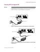

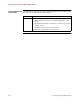

Power Up
Sequence
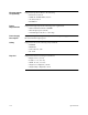
When the Vanguard 342 power cord is plugged into the power supply outlet, you will
see the following power up sequence:
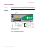
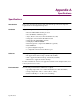
Detailed FT1/FE1
LED
The FT1/FE1 daughtercards have one LED located on the rear panel. Software
controls the LED and indicates the following when ON or OFF:
• ON - Alarm condition data path is disrupted, refer to the FT1/FE1 interface
statistics for more information on the problem.
• OFF - Normal operation exists.
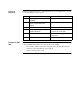
Stage when... ...this indicates
1 Power (PWR) LED turns on
(GREEN)
Vanguard is receiving power.
2 PWR LED remains on and the
Status (STAT) LED blinks
(RED).
Diagnostics are starting.
3 PWR LED blinks. Diagnostics are executed.
4 PWR LED remains on and the
STAT LED blinks.
Indicates software is being
downloaded from FLASH.
5 PWR LED blinks. Software is initializing your system
configuration.
6 PWR LED remains on. Your system is running.