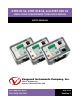
ATRT-01 S2, ATRT-01B S2, and ATRT-01D S2 SINGLE PHASE TRANSFORMER TURNS-RATIO METERS USER’S MANUAL Vanguard Instruments Company, Inc. 1520 S. Hellman Ave.
ATRT-01 S2, ATRT-01B S2, AND ATRT-01D S2 USER’S MANUAL REV 2 SAFETY SUMMARY This manual applies to the ATRT-01 S2, ATRT-01B S2, and ATRT-1D S2 current transformer turns-ratio meters. The operating procedures are virtually the same for all three models, and any differences are clearly described where applicable.
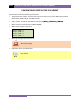
REV 2 ATRT-01 S2, ATRT-01B S2, AND ATRT-01D S2 USER’S MANUAL TABLE OF CONTENTS CONVENTIONS USED IN THIS DOCUMENT ..................................................................................... 1 1.0 INTRODUCTION .................................................................................................................... 2 1.1 General Description and Features ................................................................................... 2 1.2 Technical Specifications .....................
ATRT-01 S2, ATRT-01B S2, AND ATRT-01D S2 USER’S MANUAL REV 2 LIST OF TABLES Table 1. ATRT-01 S2 Technical Specifications ................................................................................. 4 Table 2. ATRT-01B S2 Technical Specifications ............................................................................... 5 Table 3. ATRT-01D S2 Technical Specifications .............................................................................. 6 Table 4.
REV 2 ATRT-01 S2, ATRT-01B S2, AND ATRT-01D S2 USER’S MANUAL CONVENTIONS USED IN THIS DOCUMENT This document uses the following conventions: • The general term “ATRT” is used in this manual to refer to any of the ATRT-01 S2 models (ATRT-01 S2, ATRT-01B S2, and ATRT-1D S2). • A key, switch, or knob on the ATRT is indicated as [KEY], [SWITCH], [KNOB].
ATRT-01 S2, ATRT-01B S2, AND ATRT-01D S2 USER’S MANUAL 1.0 INTRODUCTION 1.1 General Description and Features REV 2 The ATRT-01 S2 is Vanguard’s third-generation micro-processor-based, single-phase, automatic, transformer-turns-ratio tester. This portable test equipment is offered in three models: the ATRT-01 S2, ATRT-01B S2, and ATRT-01D S2. The ATRT-01 S2 is ac-line powered; the ATRT-01B S2 is ac-line or rechargeable-battery powered, and the ATRT-01D S2 is powered by six D-cells.
REV 2 ATRT-01 S2, ATRT-01B S2, AND ATRT-01D S2 USER’S MANUAL Battery Power for Exceptional Portability The ATRT-01B S2 is powered by a 6-Volt, 7 Ampere-hour, lead-acid battery. The high capacity battery, coupled with the ATRT-01B S2’s low power consuming circuitry, allows the unit to be used continuously for up to 6 hours between re-charges. A built-in charger lets the unit be used while the battery is being charged. The ATRT-01D S2 uses 6 D-cell batteries.
ATRT-01 S2, ATRT-01B S2, AND ATRT-01D S2 USER’S MANUAL 1.2 REV 2 Technical Specifications 1.2.1. ATRT-01 S2 Technical Specifications Table 1. ATRT-01 S2 Technical Specifications TYPE Portable, automatic, single-phase transformer turns ratio meter INPUT POWER 120 or 240Vac (Selectable), 50/60Hz (See section 2.1) MEASUREMENT METHOD ANSI/IEEE C57.12.90 RATIO MEASURING RANGE 0.8 – 15,000 (5-digit resolution) TURNS-RATIO ACCURACY 0.800 – 1,999 (±0.1%), 2,000 – 3,999 (±0.
REV 2 ATRT-01 S2, ATRT-01B S2, AND ATRT-01D S2 USER’S MANUAL 1.2.2. ATRT-01B S2 Technical Specifications Table 2. ATRT-01B S2 Technical Specifications TYPE Portable, automatic, single-phase transformer turns ratio meter INPUT POWER SLA battery (90–240Vac, 50/60Hz). Delivers up to 6-hours of operation. MEASUREMENT METHOD ANSI/IEEE C57.12.90 RATIO MEASURING RANGE 0.8 – 15,000 (5-digit resolution) TURNS-RATIO ACCURACY 0.800–1,999 (±0.1%), 2,000–3,999 (±0.25%), 4,000–15,000 (±1.
ATRT-01 S2, ATRT-01B S2, AND ATRT-01D S2 USER’S MANUAL REV 2 1.2.3. ATRT-01D S2 Technical Specifications Table 3. ATRT-01D S2 Technical Specifications TYPE Portable, automatic, single-phase transformer turns ratio meter INPUT POWER 6 D Cells (250-test capacity) MEASUREMENT METHOD ANSI/IEEE C57.12.90 RATIO MEASURING RANGE 0.8 – 15,000 (5-digit resolution) TURNS-RATIO ACCURACY 0.800–1,999 (±0.1%), 2,000–3,999 (±0.25%), 4,000–15,000 (±1.
REV 2 1.3 ATRT-01 S2, ATRT-01B S2, AND ATRT-01D S2 USER’S MANUAL Controls and Indicators The ATRT-01 S2, ATRT-01B S2, and ATRT-01D S2 controls and indicators are shown in Figure 1, Figure 2, and Figure 3, respectively. A leader line with an index number points to each control and indicator, which is cross-referenced to a functional description in the corresponding table. The purpose of the controls and indicators may seem obvious, but users should familiarize themselves with them before using the ATRT.
ATRT-01 S2, ATRT-01B S2, AND ATRT-01D S2 USER’S MANUAL REV 2 Figure 1. ATRT-01 S2 Controls and Indicators Table 4. Functional Descriptions of ATRT-01 S2 Controls and Indicators Item Number Panel Markings 1 RS-232C Functional Description RS-232C computer interface port. Data rate is set to 19,200 baud, 1 start bit, 8 data bits, 2 stop bits, and no parity bit. 2 Back-lit LCD screen (20 characters by 4 lines), viewable in bright sunlight and low-light levels. 3 Rugged alpha-numeric keypad.
REV 2 ATRT-01 S2, ATRT-01B S2, AND ATRT-01D S2 USER’S MANUAL Figure 2. ATRT-01B S2 Controls and Indicators Table 5. Functional Descriptions of ATRT-01B S2 Controls and Indicators 9 Item Number Panel Markings 1 RS-232C Functional Description RS-232C computer interface port. Data rate is set to 19,200 baud, 1 start bit, 8 data bits, 2 stop bits, and no parity bit. 2 Back-lit LCD screen (20 characters by 4 lines), viewable in bright sunlight and low-light levels. 3 Rugged alpha-numeric keypad.
ATRT-01 S2, ATRT-01B S2, AND ATRT-01D S2 USER’S MANUAL REV 2 Figure 3. ATRT-01D S2 Controls and Indicators Table 6. Functional Descriptions of ATRT-01D S2 Controls and Indicators Item Number Panel Markings 1 RS-232C Functional Description RS-232C computer interface port. Data rate is set to 19,200 baud, 1 start bit, 8 data bits, 2 stop bits, and no parity bit. 2 Back-lit LCD screen (20 characters by 4 lines), viewable in bright sunlight and low-light levels. 3 Rugged alpha-numeric keypad.
REV 2 ATRT-01 S2, ATRT-01B S2, AND ATRT-01D S2 USER’S MANUAL 2.0 PRE-TEST SETUP 2.1 ATRT-01 S2 Operating Voltages The ATRT-01 S2 is powered by ac line voltage only. The operating voltage is preset at the factory and is selectable between 100-120 Vac, 50/60 Hz or 200-240 Vac, 50/60 Hz. Only the reference transformer requires voltage selection for the different operating voltages. The voltage is set by placing jumper(s) on the transformer (part number 200466-1) as shown in Figure 5 and Figure 6.
ATRT-01 S2, ATRT-01B S2, AND ATRT-01D S2 USER’S MANUAL REV 2 Figure 5. ATRT-01 S2 100 – 120 Vac Jumper Settings Figure 6.
REV 2 2.2 ATRT-01 S2, ATRT-01B S2, AND ATRT-01D S2 USER’S MANUAL ATRT-01B S2 Operating Power The ATRT-01B S2 is powered by a rechargeable (6 Vdc / 7 AH) sealed lead acid gel battery. The unit can operate continuously for up to 6 hours between charges. It can also be used while charging. Plugging the ATRT-01B S2 into an ac power outlet after the battery is fully charged will not damage the battery. NOTES 2.3 • It is recommended that the ATRT-01B S2 be plugged into an ac outlet when it is not in use.
ATRT-01 S2, ATRT-01B S2, AND ATRT-01D S2 USER’S MANUAL 3.0 OPERATING PROCEDURES 3.1 ATRT Transformer Connection Diagrams REV 2 Figure 7.
REV 2 ATRT-01 S2, ATRT-01B S2, AND ATRT-01D S2 USER’S MANUAL Figure 8.
ATRT-01 S2, ATRT-01B S2, AND ATRT-01D S2 USER’S MANUAL REV 2 Figure 9.
REV 2 ATRT-01 S2, ATRT-01B S2, AND ATRT-01D S2 USER’S MANUAL Figure 10.
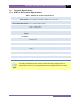
ATRT-01 S2, ATRT-01B S2, AND ATRT-01D S2 USER’S MANUAL 3.2 REV 2 Setting the Test Voltage The ATRT offers two test voltages, 8 Vac and 40 Vac. The unit always defaults to 40 Vac at power-on. The 8 Vac test voltage can be used in situations where the 40 Vac excitation voltage may saturate the CT’s. To set the test voltage: a. Turn on the unit and start from the “ START-UP” menu: 1.TEST XFMR 06/02/10 2.SETUP 15:33:10 3.CALCULATOR Press the [2] key (SETUP). b. The following screen will be displayed: 1.
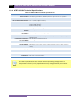
REV 2 3.3 ATRT-01 S2, ATRT-01B S2, AND ATRT-01D S2 USER’S MANUAL Enabling the Computer Interface The ATRT can be connected to a computer via the RS-232C interface port. In order to remotely control the unit using the provided Transformer Turns Ratio Analysis (TTRA) software, the unit must be placed in Computer Control mode. Use the steps below to place the unit in Computer Control mode: a. Start from the “START-UP” menu: 1.TEST XFMR 06/02/10 2.SETUP 15:33:10 3.CALCULATOR Press the [2] key (SETUP). b.
ATRT-01 S2, ATRT-01B S2, AND ATRT-01D S2 USER’S MANUAL 3.4 REV 2 Setting the Date and Time To set the date and time: a. Start from the “START-UP” menu: 1.TEST XFMR 06/02/10 2.SETUP 15:33:10 3.CALCULATOR Press the [2] key (SETUP). b. The following screen will be displayed: 1.SET TIME 2.SET TEST VOLTAGE 3.COMPUTER CONTROL Press the [2] key (SET TIME) c. The following screen will be displayed: ENTER MM-DD-YY HH:MM:SS _ Type in the date and time using the alpha-numeric keypad.
REV 2 3.5 ATRT-01 S2, ATRT-01B S2, AND ATRT-01D S2 USER’S MANUAL Performing Tests 3.5.1. Testing a Single Phase Transformer Follow the steps below to test a single phase transformer: a. Start from the “START-UP” menu: 1.TEST XFMR 06/02/10 2.SETUP 15:33:10 3.CALCULATOR Press the [1] key (TEST XFMR). b. The following screen will be displayed: XFMR CONFIGURATION: 1.SNGL PHS 2.dT-Y 3.Y-dT 4.dT-dT 5.Y-Y Press the [1] key (SNGL PHS). c. The following screen will be displayed: XFMR NAME PLATE VLTG 1. YES 2.
ATRT-01 S2, ATRT-01B S2, AND ATRT-01D S2 USER’S MANUAL REV 2 ENTER X WINDING NAME-PLATE VOLTAGE: V Type the X winding name plate voltage value using the numeric keypad. The screen will be updated as shown: ENTER H WINDING NAME-PLATE VOLTAGE: 10 V Press the [ENTER] key. Continue to step d. 2. NO Press the [2] key (NO) if you do not want to enter the transformer name plate voltage. Continue to step d. d.
REV 2 ATRT-01 S2, ATRT-01B S2, AND ATRT-01D S2 USER’S MANUAL f. The following screen will be displayed: REPEAT TEST? 1. YES 2. NO Press the [2] key (NO). You will be returned to the “START-UP” screen.
ATRT-01 S2, ATRT-01B S2, AND ATRT-01D S2 USER’S MANUAL REV 2 3.5.2. Testing a Three Phase Transformer Follow the steps below to test a three phase transformer: a. Start from the “START-UP” menu: 1.TEST XFMR 06/02/10 2.SETUP 15:33:10 3.CALCULATOR Press the [1] key (TEST XFMR). b. The following screen will be displayed: XFMR CONFIGURATION: 1.SNGL PHS 2.dT-Y 3.Y-dT 4.dT-dT 5.Y-Y Select a three-phase transformer test by pressing the corresponding key ([2] to [5]).
REV 2 ATRT-01 S2, ATRT-01B S2, AND ATRT-01D S2 USER’S MANUAL ENTER H WINDING NAME-PLATE VOLTAGE: 500 V Press the [ENTER] key. The following screen will be displayed: ENTER X WINDING NAME-PLATE VOLTAGE: V Type the X winding name plate voltage value using the numeric keypad. The screen will be updated as shown: ENTER H WINDING NAME-PLATE VOLTAGE: 10 V Press the [ENTER] key. Continue to step e. 2. NO Press the [2] key (NO) if you do not want to enter the transformer name plate voltage. Continue to step e. e.
ATRT-01 S2, ATRT-01B S2, AND ATRT-01D S2 USER’S MANUAL REV 2 The Phase A test results will be displayed on the LCD screen when testing has finished: RATIO +15.003 mA 001 % DIFF 0.02 “ENTER” TO CONTINUE Press the [ENTER] key to continue. g.
REV 2 j. ATRT-01 S2, ATRT-01B S2, AND ATRT-01D S2 USER’S MANUAL The following screen will be displayed while the test is being performed: DYN 1 TRANSFORMER PLEASE WAIT... The Phase A, B, and C test results will be displayed on the LCD screen when testing has finished: Press any key to continue. k. The following screen will be displayed: REPEAT TEST? 1. YES 2. NO Press the [2] key (NO). You will be returned to the “START-UP” menu.
ATRT-01 S2, ATRT-01B S2, AND ATRT-01D S2 USER’S MANUAL REV 2 3.5.3. Performing a Quick Test The ATRT provides a Quick Test mode that can be used to measure a transformer’s turns ratio by only pressing a single button. To initiate a Quick Test: a. Start from the “START-UP” menu: 1.TEST XFMR 06/02/10 2.SETUP 15:33:10 3.CALCULATOR Press and hold down the [START] key. b.
REV 2 ATRT-01 S2, ATRT-01B S2, AND ATRT-01D S2 USER’S MANUAL 3.5.4. Performing a Single Phase Transformer Test Using Preset Voltage Table The ATRT is pre-programmed with 46 transformer name plate voltages. These pre-programmed values can be used to quickly test a single phase transformer’s turns ratio and compare the test results against the name plate voltage. Please see Table 8 for a list of the pre-programmed name plate voltages.
ATRT-01 S2, ATRT-01B S2, AND ATRT-01D S2 USER’S MANUAL REV 2 Please see Figure 11 below for a description of the test results elements. Figure 11. Test Results Elements In order for a test to pass, the error reading must be less than or equal to 0.5% and the winding must be in-phase (+).
REV 2 ATRT-01 S2, ATRT-01B S2, AND ATRT-01D S2 USER’S MANUAL Table 8.
ATRT-01 S2, ATRT-01B S2, AND ATRT-01D S2 USER’S MANUAL REV 2 APPENDIX A – TRANSFORMER VECTOR GROUP CODES Utility power transformers manufactured in accordance with IEC specifications have a Rating Plate attached in a visible location. This plate contains a list of the transformer's configuration and operating specifications. One such rating is the winding configuration and phasedisplacement code.
REV 2 ATRT-01 S2, ATRT-01B S2, AND ATRT-01D S2 USER’S MANUAL APPENDIX B – Common ANSI Transformer Descriptions 33
ATRT-01 S2, ATRT-01B S2, AND ATRT-01D S2 USER’S MANUAL REV 2 34
REV 2 35 ATRT-01 S2, ATRT-01B S2, AND ATRT-01D S2 USER’S MANUAL
ATRT-01 S2, ATRT-01B S2, AND ATRT-01D S2 USER’S MANUAL REV 2 36
REV 2 37 ATRT-01 S2, ATRT-01B S2, AND ATRT-01D S2 USER’S MANUAL
ATRT-01 S2, ATRT-01B S2, AND ATRT-01D S2 USER’S MANUAL REV 2 38
REV 2 39 ATRT-01 S2, ATRT-01B S2, AND ATRT-01D S2 USER’S MANUAL
ATRT-01 S2, ATRT-01B S2, AND ATRT-01D S2 USER’S MANUAL REV 2 40
REV 2 ATRT-01 S2, ATRT-01B S2, AND ATRT-01D S2 USER’S MANUAL APPENDIX C – CEI/IEC 60076-1 Transformer Descriptions 41
ATRT-01 S2, ATRT-01B S2, AND ATRT-01D S2 USER’S MANUAL REV 2 42
REV 2 43 ATRT-01 S2, ATRT-01B S2, AND ATRT-01D S2 USER’S MANUAL
ATRT-01 S2, ATRT-01B S2, AND ATRT-01D S2 USER’S MANUAL REV 2 44
REV 2 45 ATRT-01 S2, ATRT-01B S2, AND ATRT-01D S2 USER’S MANUAL
ATRT-01 S2, ATRT-01B S2, AND ATRT-01D S2 USER’S MANUAL REV 2 46
REV 2 47 ATRT-01 S2, ATRT-01B S2, AND ATRT-01D S2 USER’S MANUAL
ATRT-01 S2, ATRT-01B S2, AND ATRT-01D S2 USER’S MANUAL REV 2 APPENDIX D – Australian Std.
REV 2 49 ATRT-01 S2, ATRT-01B S2, AND ATRT-01D S2 USER’S MANUAL
ATRT-01 S2, ATRT-01B S2, AND ATRT-01D S2 USER’S MANUAL REV 2 50
REV 2 51 ATRT-01 S2, ATRT-01B S2, AND ATRT-01D S2 USER’S MANUAL
ATRT-01 S2, ATRT-01B S2, AND ATRT-01D S2 USER’S MANUAL REV 2 52
REV 2 53 ATRT-01 S2, ATRT-01B S2, AND ATRT-01D S2 USER’S MANUAL
ATRT-01 S2, ATRT-01B S2, AND ATRT-01D S2 USER’S MANUAL REV 2 54
1520 S. Hellman Ave • Ontario, CA 91761 • USA Phone: 909-923-9390 • Fax: 909-923-9391 www.vanguard-instruments.com Copyright © 2010 by Vanguard Instruments Company, Inc. ATRT-01/01B/01D S2 User’s Manual • Revision 2.