CT-7500 S2TM DIGITAL CIRCUIT BREAKER ANALYZER USER’S MANUAL Vanguard Instruments Company, Inc. 1520 S. Hellman Ave.
CT-7500 S2 USER’S MANUAL REV 2 SAFETY SUMMARY FOLLOW EXACT OPERATING PROCEDURES Any deviation from the procedures described in this User’s Manual may create one or more safety hazards, may damage the CT-7500 S2, or cause errors in the test results. Vanguard Instruments Company, Inc. assumes no liability for unsafe or improper use of the CT-7500 S2.
REV 2 CT-7500 S2 USER’S MANUAL TABLE OF CONTENTS CONVENTIONS USED IN THIS DOCUMENT ..................................................................................... 1 1.0 INTRODUCTION .................................................................................................................... 2 1.1 General Description and Features ................................................................................... 2 1.2 Technical Specifications ...................................................
CT-7500 S2 USER’S MANUAL REV 2 3.4 Working With Test Plans ................................................................................................ 77 3.4.1. Recalling a Breaker Test Plan for Use ..................................................................... 77 3.4.2. Printing a Directory of Test Plans Stored in the CT-7500 S2’s Memory................. 80 3.4.3. Printing a Breaker Test Plan ................................................................................... 82 4.
REV 2 CT-7500 S2 USER’S MANUAL LIST OF FIGURES Figure 1. CT-7500 S2 Controls and Indicators ................................................................................. 6 Figure 2. CT-7500 S2 Operating Voltage Setting Switch ................................................................. 8 Figure 3. Typical 3-Phase Circuit Breaker Connections ................................................................ 10 Figure 4. Typical Connections for Series Contact Circuit Breaker .........................
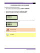
CT-7500 S2 USER’S MANUAL REV 2 CONVENTIONS USED IN THIS DOCUMENT This document uses the following conventions: • A key or switch on the CT-7500 S2 is indicated as [KEY] and [SWITCH]. • Menu options are referenced as (MENU OPTION). • Screen and menu names are referenced as “SCREEN/MENU NAME”. • The terms “test record” and “test shot” are used interchangeably. • CT-7500 S2 LCD screen output is shown as: 1. OPTION 2. OPTION 3. OPTION 4.
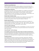
REV 2 CT-7500 S2 USER’S MANUAL 1.0 INTRODUCTION 1.1 General Description and Features The CT-7500 S2 is an easy to use, stand-alone, microprocessor-driven EHV circuit-breaker analyzer. It can operate either in Time-Travel analyzer mode or in Quick-Shot mode (for on-line timing). In Time-Travel mode, the CT-7500 S2 can fully analyze a circuit-breaker’s performance by testing the contact time, stroke, velocity, over-travel, and contact wipe.
CT-7500 S2 USER’S MANUAL REV 2 Trip/Close Current Monitoring A built-in Hall-effect current sensor records the Trip/Close current level and duration. The breaker’s operate-coil current waveform duration (effectively, a performance "fingerprint" or "current profile") can be used as a diagnostic tool for analyzing a breaker’s performance.
REV 2 CT-7500 S2 USER’S MANUAL Diagnostic Capabilities The CT-7500 S2 can perform diagnostics on its internal electronics. Diagnostics can be performed to verify contact cable connections and to test the travel transducer’s electronics. User Interface The CT-7500 S2 features a back-lit LCD screen (20 characters by 4 lines) that is viewable in both bright sunlight and low-light levels. A rugged, 16-key, membrane keypad is used to control the unit. Built-in Thermal Printer The CT-7500 S2’s built-in 4.
CT-7500 S2 USER’S MANUAL 1.2 REV 2 Technical Specifications Table 1. CT-7500 S2 Technical Specifications TYPE PHYSICAL SPECIFICATIONS INPUT POWER DRY-CONTACT INPUTS TIMING WINDOWS TIMING RESOLUTIONS TIMING ACCURACY DRY-CONTACT CHANNEL PROTECTION DRY-CONTACT DETECTION RANGE RESISTOR DETECTION RANGE CT CURRENT SENSOR Portable circuit-breaker analyzer 16”W x 11”H x 14”D (40.6 cm x 29.9 cm x 35.6 cm); Weight: less than 25 lbs (11.
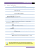
REV 2 1.3 CT-7500 S2 USER’S MANUAL CT-7500 S2 Controls and Indicators The CT-7500 S2’s controls and indicators are shown in Figure 1 below. A leader line with an index number points to each control and indicator, which is cross-referenced to a functional description in Table 2. The table describes the function of each item on the control panel. The purpose of the controls and indicators may seem obvious, but users should become familiar with them before using the CT-7500 S2.
CT-7500 S2 USER’S MANUAL REV 2 Table 2. Functional Descriptions of CT-7500 S2 Controls and Indicators Item Number Panel Markings Functional Description 1 CONTACT INPUT (C1-C12) Female connectors for the contact channels. The CT-7500-12 S2 is pictured with 12 channels. 2 0-300V V1 3-pin connector. V1 voltage input channel is dedicated to monitoring circuit breaker DC power supply or coil voltages. Voltage sensing range is from 0-255 volts, dc or peak ac. 3 0-300V V2 3-pin connector.
REV 2 CT-7500 S2 USER’S MANUAL 2.0 PRE-TEST SETUP 2.1 Operating Voltages The CT-7500 S2’s operating voltage is selectable between 110-120 Vac, 50/60 Hz and 220-240 Vac, 50/60 Hz. In older production models of the CT-7500 S2, the operating voltage is set by the voltage selection switch as shown in Figure 2. To change the voltage setting, remove the CT7500 S2 from its enclosure, locate the voltage setting switch on the right side of the unit, and set the new operating voltage.
CT-7500 S2 USER’S MANUAL 2.3 REV 2 Printer Paper Control To advance the thermal printer paper, press and release the [PAPER ∧ Contrast] key. To retract the thermal printer paper, press and release the [PAPER ∨ Contrast] key. 2.4 Printer Paper The CT-7500 S2’s built-in thermal printer uses 4.5-inch wide thermal paper for printing test results. To maintain the highest print quality and to avoid paper jams, the use of thermal paper supplied by Vanguard Instruments Company is highly recommended.
REV 2 CT-7500 S2 USER’S MANUAL 3.0 OPERATING PROCEDURES 3.1 Cable Connections 3.1.1. Contact Cable Connections A typical contact cable connection to a circuit breaker is shown in Figure 3. Red and black clips are connected across the circuit contact phases A, B, and C. A typical circuit breaker with series contacts is shown in Figure 4. NOTE It is advisable to ground one side of the contacts for most testing purposes.
CT-7500 S2 USER’S MANUAL REV 2 Figure 4.
REV 2 CT-7500 S2 USER’S MANUAL 3.1.2. Initiate Cable Connections The CT-7500 S2 can trip or close breakers through a solid-state device operating on any AC or DC control voltage ranging from 10 to 300 Volts. Both the trip and close circuits are protected by 5 Ampere fuses. A typical DC trip and DC close control circuit connection is shown in Figure 5. A typical DC trip and AC close control circuit connection is shown in Figure 6. Figure 5.
CT-7500 S2 USER’S MANUAL REV 2 Figure 6.
REV 2 CT-7500 S2 USER’S MANUAL 3.1.3. Analog and Digital Voltage Monitoring Connections The analog voltage input “V1” can monitor a breaker’s DC control voltage during an operation. The analog voltage input records the nominal DC voltage at no load and the minimum DC voltage while the Trip or Close coil is energized. The nominal and minimal voltage readings are printed on a tabulated report, and the analog waveforms are plotted in graphical format.
CT-7500 S2 USER’S MANUAL REV 2 3.1.4. External Trigger Input Connections The External Trigger Mode can be used to start recording data when the CT-7500 S2 senses a voltage. A typical application for the External Trigger Mode is to time a circuit breaker in a Close operation and to start timing only when the Close coil is energized, thus bypassing the 52X relay delay time.
REV 2 CT-7500 S2 USER’S MANUAL 3.1.5. Digital Transducer Connection A typical digital transducer connection is shown in Figure 9. Figure 9.
CT-7500 S2 USER’S MANUAL REV 2 3.1.6. Resistor Type Transducer Connection The CT-7500 S2 provides one channel for resistor type transducers. The transducer resistance input can range from 200 Ohms to 10K Ohms. The CT-7500 S2 supplies a 5 Vdc reference voltage to power the resistor type transducer. The sense voltage is translated into a travel distance based on the transducer calibration parameters. The user is required to setup the resistor transducer before performing a test.
REV 2 CT-7500 S2 USER’S MANUAL 3.1.7. On-line Test AC Current Sensor Connection A typical CT-7500 S2 AC current sensor connection is shown in Figure 11. The non-contact AC current sensor must be connected to one of the circuit breaker bushing CT terminals. A minimum current of 100 mA is required for the CT-7500 S2 AC current sensor. Figure 11.
CT-7500 S2 USER’S MANUAL REV 2 3.1.8. Pre-Test Setup 3.1.9. Entering Test Record Header Information You can enter the test record header information before performing tests. The record header includes identifying information such as the company, station, circuit, model number, etc. Once the header information has been entered, it will apply to all subsequent test records. To enter the header information: a.
REV 2 CT-7500 S2 USER’S MANUAL d. The following screen will be displayed: COMPANY: ↑↓ TO POSITION “ENTER” TO ACCEPT Type the company name using the alpha-numeric keypad. When pressing a key, the corresponding number on the key will be displayed first. Pressing the key again will display the first letter on the key. Pressing the key again will display the second letter on the key. For example, to type the letter “A”, you must press the [2] key twice.
CT-7500 S2 USER’S MANUAL REV 2 h. The following screen will be displayed: MODEL: ↑↓ TO POSITION “ENTER” TO ACCEPT Type the model information using the alpha-numeric keypad and then press the [ENTER] key. i. The following screen will be displayed: SERIAL NUMBER: ↑↓ TO POSITION “ENTER” TO ACCEPT Type the serial number using the alpha-numeric keypad and then press the [ENTER] key. j.
REV 2 CT-7500 S2 USER’S MANUAL 3.1.10. Setting the Clock Follow the steps below to set the CT-7500 S2’s internal clock: a. Start from the “START-UP” menu: 1. TIME BRKR 02/17/11 2. GET RSLT 15:05:15 3. SETUP 4. DIAGNOSTICS Press the [3] key (SETUP). b. The following screen will be displayed: 1. ANALYSIS POINTS 2. MEASUREMENT UNITS 3. SAVE / RESTORE 4. NEXT PAGE Press the [4] key (NEXT PAGE). c. The following screen will be displayed: 1. SHOT DESCRIPTION 2. NUMBER OF CHANNELS 3. SET DATE & TIME 4.
CT-7500 S2 USER’S MANUAL REV 2 3.1.11. Configuring the Automatic Printing Feature The CT-7500 S2 can be configured to print graphs and tabulated results automatically after each test. To configure the automatic printing feature: a. Start from the “START-UP” menu: 1. TIME BRKR 02/17/11 2. GET RSLT 14:16:11 3. SETUP 4. DIAGNOSTICS Press the [3] key (SETUP). b. The following screen will be displayed: 1. ANALYSIS POINTS 2. MEASUREMENT UNITS 3. SAVE / RESTORE 4. NEXT PAGE Press the [4] key (NEXT PAGE). c.
REV 2 CT-7500 S2 USER’S MANUAL 3.1.12. Setting the Units of Measure The CT-7500 S2 supports and displays both English and Metric calculations. You can switch between the English and Metric systems using the steps below: a. Start from the “START-UP” menu: 1. TIME BRKR 02/17/11 2. GET RSLT 13:08:25 3. SETUP 4. DIAGNOSTICS Press the [3] key (SETUP). b. The following screen will be displayed: 1. ANALYSIS POINTS 2. MEASUREMENT UNITS 3. SAVE / RESTORE 4. NEXT PAGE Press the [2] key (MEASUREMENT UNITS). c.
CT-7500 S2 USER’S MANUAL REV 2 3.1.13. Setting the Open Timing Analysis Points Two analysis points are used to calculate the velocity of the circuit breaker in the open operation. To configure the OPEN timing analysis points: a. Start from the “START-UP” menu: 1. TIME BRKR 02/17/11 2. GET RSLT 09:04:05 3. SETUP 4. DIAGNOSTICS Press the [3] key (SETUP). b. The following screen will be displayed: 1. ANALYSIS POINTS 2. MEASUREMENT UNITS 3. SAVE / RESTORE 4. NEXT PAGE Press the [1] key (ANALYSIS POINTS). c.
REV 2 CT-7500 S2 USER’S MANUAL The following screen will be displayed: OPEN ANALYSIS PT 1 % OF TOTAL STROKE VALUE: 00% “ENTER” TO CONFIRM Type the percentage value using the numeric keypad and then press the [ENTER] key. Continue to step e. 2. DIST FROM CLOSE Press the [2] key (DIST FROM CLOSE) to set the open analysis point #1 as a distance from the contact’s close position. The distance from close range is selectable from 00.0 inch to 99.99 inches or from 0.0 to 999.0 millimeters.
CT-7500 S2 USER’S MANUAL REV 2 e. The following screen will be displayed: OPEN ANALYSIS PT 2 1. PERCENT OF STROKE 2. DIST FROM CLOSE 3. CONTACT +/- TIME 1. PERCENT OF STROKE Press the [1] key (PERCENT OF STROKE) to set the open analysis point #2 as a percentage of the total stroke value. The following screen will be displayed: OPEN ANALYSIS PT 2 % OF TOTAL STROKE VALUE: 00% “ENTER” TO CONFIRM Type the percentage value using the numeric keypad and then press the [ENTER] key.
REV 2 CT-7500 S2 USER’S MANUAL The following screen will be displayed: OPEN ANALYSIS PT 2 ENTER TIME FROM CH1 TIME (mS): 000.0 “ENTER” TO CONFIRM Type the time value using the numeric keypad and then press the [ENTER] key. The analysis points will be set and you will be returned to the “START-UP” menu. 2. CONTACT MINUS TIME Press the [2] key to select the CONTACT MINUS TIME option.
CT-7500 S2 USER’S MANUAL REV 2 3.1.14. Selecting the Contact Cycle Reading Frequency The contact time is printed on the tabulated test results printout in both milliseconds and cycles. The cycle readings can be in 50 Hz or 60 Hz. You can select the preferred frequency using the steps below: a. Start from the “START-UP” menu: 1. TIME BRKR 02/21/11 2. GET RSLT 09:04:05 3. SETUP 4. DIAGNOSTICS Press the [3] key (SETUP). b. The following screen will be displayed: 1. ANALYSIS POINTS 2. MEASUREMENT UNITS 3.
REV 2 CT-7500 S2 USER’S MANUAL f. The following confirmation screen will be displayed: 60 Hz SET Press any key to return to the “START-UP” menu. Sample tabulated test results are shown in Figure 12 and Figure 13. If the frequency value is changed, the cycle values are automatically recalculated by the CT-7500 S2.
CT-7500 S2 USER’S MANUAL REV 2 Frequency Set to 50 Hz Cycle reading at 50 Hz Figure 12. Typical 50 Hz Tabulated Test Results Frequency set to 60 Hz Cycle reading at 60 Hz Figure 13.
REV 2 CT-7500 S2 USER’S MANUAL 3.1.15. Configuring the Channel Settings The CT-7500 S2 is available with 3, 6, or 12 contact inputs. Since most common timing applications require the use of only 3 contact timing channels and one travel transducer channel, there is no need to print data for more than 3 timing channels and one transducer channel on the graphic and tabulated reports.
CT-7500 S2 USER’S MANUAL REV 2 Press either the [1] key (3 CONTACTS) or the [2] key (6 CONTACTS) to select the corresponding number of contact channels. e. The following screen will be displayed: 1. TRANSDUCER 1 2. TRANSDUCER 1,2 3. TRANSDUCER 1,2,3 Select the number of transducer channels by pressing either the [1], [2], or [3] key. The configuration information will be saved and you will be returned to the “START-UP” menu.
REV 2 CT-7500 S2 USER’S MANUAL 3.1.16. Configuring the Contact Filter Settings Although the CT-7500 S2 automatically detects the contact time using its own algorithm, it also allows the user to enter a custom filter value. The value can be between 1 and 300. A filter setting of 1 allows the CT-7500 S2 to pick up the first contact transition time after the resistor contact activity is detected.
CT-7500 S2 USER’S MANUAL REV 2 Filter Setting @ 1 will select this contact time Filter Setting @ 300 will select this contact time Filter Setting @ 1 will select this contact time Filter Setting @ 300 will select this contact time Figure 14.
REV 2 CT-7500 S2 USER’S MANUAL 3.1.17. Configuring the Transducer Encoder Filter Setting In a typical 1-second timing record, the CT-7500 S2 records 20,000 data points for each of the contact channels, digital transducer channels, voltage input channels, CT channel, DCR channel, resistor transducer channel, and initiate current channel. In most circuit breaker timing applications, the breaker activities end after 200 milliseconds.
CT-7500 S2 USER’S MANUAL REV 2 d. The following screen will be displayed: ENTER FILTER TIME (010 – 999) Type the filter time (in milliseconds) using the numeric keypad, and then press the [ENTER] key to return to the “START-UP” menu. The CT-7500 S2 will not record any transducer encoder data after this time.
REV 2 CT-7500 S2 USER’S MANUAL 3.1.18. Configuring the Digital Rotary Transducer Settings A rotary transducer requires the user to enter the defined linear distance in millimeters or inches per one degree of rotary motion. Follow the steps below to configure the settings for a digital rotary transducer: a. Start from the “START-UP” menu: 1. TIME BRKR 02/21/11 2. GET RSLT 13:21:25 3. SETUP 4. DIAGNOSTICS Press the [3] key (SETUP). b. The following screen will be displayed: 1. ANALYSIS POINTS 2.
CT-7500 S2 USER’S MANUAL REV 2 Type the desired value using the numeric keypad. You can press the [CLEAR] key to reset the value to 0.000 In/Deg. Press the [ENTER] key to save the new value. You will be returned to the “START-UP” menu. 2. METRIC (MM/deg) Press the [2] key to enter the rotary encoder linear distance per degree using Metric units. The following screen will be displayed: MM/DEGREE 12.70 MM/Deg Type the desired value using the numeric keypad.
REV 2 CT-7500 S2 USER’S MANUAL 3.1.19. Configuring the Resister Type Transducer Settings The CT-7500 S2 provides one optional channel for a resistor type transducer. The transducer must be configured before it can be used with the CT-7500 S2. Up to 9 resistor transducer setups can be stored in the CT-7500 S2’s Flash EEPROM. When a resistive transducer is used with the CT-7500 S2, it is shown as transducer #1 on the timing report as shown in Figure 16.
CT-7500 S2 USER’S MANUAL REV 2 e. The following screen will be displayed: RESISTIVE ENCODER 1. ENGLISH (IN/Volt) 2. METRIC (MM/Volt) Press the [1] key to enter the transducer travel distance per volt using English units, or press the [2] key to enter the transducer travel distance per volt using Metric units. f. The following screen will be displayed: MOVE RES ENCODER TO REFERENCE POSITION. “ENTER” TO CONTINUE Move the transducer to the reference position and press the [ENTER] key. g.
REV 2 j. CT-7500 S2 USER’S MANUAL The following screen will be displayed: ENTER SETUP NUMBER TO SAVE (1-9): Enter a setup number from 1 to 9 using the numeric keypad. k. The following screen will be displayed: “ENTER” TO SAVE SETUP NUMBER 1 Press the [ENTER] key to save the setup. If a setup already exists at the selected memory location, it will be over-ridden by the new setup values. NOTE l. The following screen will be displayed while the setup is being saved: SAVE IN PROGRESS PLEASE WAIT...
CT-7500 S2 USER’S MANUAL REV 2 Loading a Resistor Type Transducer Setup Follow the steps below to load a resistor type transducer setup: a. Start from the “START-UP” menu: 1. TIME BRKR 02/21/11 2. GET RSLT 14:04:05 3. SETUP 4. DIAGNOSTICS Press the [3] key (SETUP). b. The following screen will be displayed: 1. ANALYSIS POINTS 2. MEASUREMENT UNITS 3. SAVE / RESTORE 4. NEXT PAGE Press the [2] key (MEASUREMENT UNITS). c. The following screen will be displayed: SELECT UNITS: 1. ENGLISH 2. METRIC 3. ROT ENC 4.
REV 2 CT-7500 S2 USER’S MANUAL If there is no setup stored in the selected memory location, the following screen will be displayed: NOTE SETUP NOT FOUND Press any key to return to the “START-UP” menu. f. The following screen will be displayed: SETUP NUMBER: 1 NOTE ENGLISH “ENTER” TO CONTINUE Press the [ENTER] key to load the selected setup. g. The following screen will be displayed: SETUP LOADED! Press any key to return to the “START-UP” menu.
CT-7500 S2 USER’S MANUAL REV 2 c. The following screen will be displayed: SELECT UNITS: 1. ENGLISH 2. METRIC 3. ROT ENC 4.RES ENC Press the [4] key (RES ENC). d. The following screen will be displayed: RESISTIVE ENCODER 1. CREATE NEW SETUP 2. LOAD SETUP 3. PRINT SETUP DIR Press the [3] key (PRINT SETUP DIR). The setup directory will be printed and you will be returned to the “START-UP” menu. A sample resistor type transducer setup directory printout is shown in Figure 15. Figure 15.
REV 2 CT-7500 S2 USER’S MANUAL Resistive Type Transducer Indicator Figure 16.
CT-7500 S2 USER’S MANUAL 3.2 REV 2 Performing Circuit Breaker Timing Tests The CT-7500 S2 can initiate the breaker operation and perform a timing test on the following operations: • • • • • OPEN CLOSE OPEN-CLOSE CLOSE-OPEN OPEN-CLOSE-OPEN The CT-7500 S2 can start the OPEN-CLOSE operations without a delay or by using a programmable delay between the OPEN and CLOSE commands.
REV 2 CT-7500 S2 USER’S MANUAL 3.2.1. Timing an OPEN Operation The CT-7500 S2 can time breakers with or without insertion resistors. The insertion resistance can range from 10 to 5,000 Ohms. Any insertion resistance greater than 5,000 Ohms is detected as an open circuit. The timing results will show the main contact time and the insertion resistor contact time. Graphic reports will show the main contact and the resistor contact activities on each of the channels.
CT-7500 S2 USER’S MANUAL REV 2 c. The following screen will be displayed: TIMING WINDOW: 1. WINDOW = 1 SEC 2. WINDOW = 10 SEC 3. WINDOW = 20 SEC Press the [1] key (WINDOW = 1 SEC). NOTE The 1-second timing window is used for breaker timing. The 10 and 20second timing windows are used for long timing events such as for timing circuit-switchers. d. The following screen will be displayed: TRIGGER MODE: 1. INTERNAL TRIGGER 2. EXTERNAL TRIGGER Press the [1] key (INTERNAL TRIGGER). e.
REV 2 CT-7500 S2 USER’S MANUAL • Please see section 3.2.5 for information about printing test results. NOTES 50 • The CT-7500 S2 can be configured to print tabulated and graphics reports automatically after performing a test. Please see section 3.1.11 for further information.
CT-7500 S2 USER’S MANUAL REV 2 3.2.2. Timing a CLOSE-OPEN Operation Using Contact Channel #1 The CLOSE-OPEN operation of a breaker simulates a condition where a breaker is closed on a fault. There are three options when timing a CLOSE-OPEN operation: 1. Contact #1 CLOSE The CT-7500 S2 will initiate a CLOSE operation. The open operation is then initiated after contact channel #1 is closed. This option closes simulates the breaker closing on a fault condition in the field. 2.
REV 2 CT-7500 S2 USER’S MANUAL d. The following screen will be displayed: TRIGGER MODE: 1. INTERNAL TRIGGER 2. EXTERNAL TRIGGER Press the [1] key (INTERNAL TRIGGER). e. The following screen will be displayed: TIMING MODE: 1. OPEN 2. CLOSE 3. O-C 4. C-O 5. O-C-O Press the [4] key (C-O). f. The following screen will be displayed: C-O Second Trigger 1. Contact #1 CLOSE 2. Set DELAY 3. No DELAY 1.
CT-7500 S2 USER’S MANUAL REV 2 g. The following screen will be displayed: Hold “ARM” until test completes. “START” to Begin “STOP” to ABORT Hold down the [ARM] switch and press the [START] key. h. The following screen will be displayed: TEST IN PROGRESS Hold “ARM” until test completes. (Up to 25 seconds) Continue to hold down the [ARM] switch until testing is finished. You will be returned to the “START-UP” menu once testing is finished.
REV 2 CT-7500 S2 USER’S MANUAL 3.2.3. Timing an OPEN-CLOSE-OPEN Operation The OPEN-CLOSE-OPEN operation requires the user to enter two time delays (in milliseconds) between the circuit breaker operations. The first delay is from the first OPEN command to the CLOSE command, and the second delay is from the CLOSE command to the second OPEN command. Follow the steps below to time an OPEN-CLOSE-OPEN operation: a. Start from the “START-UP” menu: 1. TIME BRKR 02/26/11 2. GET RSLT 09:15:25 3. SETUP 4.
CT-7500 S2 USER’S MANUAL REV 2 f. The following screen will be displayed: O-C Delay in mS: (10 – 350) 200 mSec ENTER when done Using the numeric keypad, enter the time for the delay between the first OPEN command and the CLOSE command. Press the [ENTER] key. g. The following screen will be displayed: C-O Delay in mS: (10 – 350) 200 mSec ENTER when done Using the numeric keypad, enter the time for the delay between the CLOSE command and the second OPEN command. Press the [ENTER] key. h.
REV 2 CT-7500 S2 USER’S MANUAL Figure 17.
CT-7500 S2 USER’S MANUAL REV 2 Figure 18.
REV 2 CT-7500 S2 USER’S MANUAL 3.2.4. Running CT-7500 S2’s in Tandem Two or more CT-7500 S2’s can be used to time a circuit breaker that requires more contact channels than those available on the single CT-7500 S2 unit. The example below shows how to use two CT-7500-6 S2’s (6 channels each) in tandem to create a 12 contact timing apparatus. Use the steps below to configure the CT-7500 S2’s: a. Connect the Master CT-7500-6 S2 to phase A and B of the circuit breaker. b.
CT-7500 S2 USER’S MANUAL REV 2 3.2.5. Printing or Viewing Timing Results Follow the steps below to print or view the timing results after performing a circuit breaker timing test: a. After performing a timing test you will be returned to the “START-UP” menu: 1. TIME BRKR 02/25/11 2. GET RSLT 09:04:05 3. SETUP 4. DIAGNOSTICS Press the [2] key (GET RSLT). b. The following screen will be displayed: 1. PRINT TEST RESULTS 2. PLOT FULL CHART 3. PLOT EXPANSION 4. PLOT 0 – 200MS 1.
REV 2 CT-7500 S2 USER’S MANUAL 2. PLOT FULL CHART Press the [2] key to print the tabulated results WITH the full graph of the results. You will be returned to the “START-UP” menu when printing is finished. A typical test result graph is shown in Figure 21. 3. PLOT EXPANSION Press the [3] key to print the tabulated results along with a time expansion plot of the test results.
CT-7500 S2 USER’S MANUAL 4. REV 2 PLOT 0 – 200MS Press the [4] key to print the tabulated test results along with the graphic test results from 0 – 200 milliseconds. The graph and tabulated results will be printed on the thermal printer. You will be returned to the “START-UP” menu when printing is finished. Figure 20.
REV 2 CT-7500 S2 USER’S MANUAL Table 3. Descriptions of Tabulated Test Results Elements Item Number 62 Description 1 Test record number and the date and time the test was performed. 2 Test record header information (Company, Station, Circuit, etc.). 3 Type of test performed (OPEN, CLOSE, O-C, C-O, or O-C-O). 4 Contact channel times shown in milliseconds and cycles. 5 Contact channel bounce times shown in milliseconds. 6 Contact channel wipe distances in inches.
CT-7500 S2 USER’S MANUAL REV 2 Figure 21.
REV 2 CT-7500 S2 USER’S MANUAL Figure 22.
CT-7500 S2 USER’S MANUAL REV 2 Figure 23.
REV 2 CT-7500 S2 USER’S MANUAL Figure 24.
CT-7500 S2 USER’S MANUAL REV 2 Figure 25. Graphical Interpretation of an OPEN Timing Shot Figure 26.
REV 2 CT-7500 S2 USER’S MANUAL Figure 27.
CT-7500 S2 USER’S MANUAL 3.3 REV 2 Working with Test Records 3.3.1. Saving a Timing Record in Flash EEPROM After performing a test, you can store the results in the CT-7500 S2’s Flash EEPROM. To save a test record: a. Start from the “START-UP” menu: 1. TIME BRKR 02/25/11 2. GET RSLT 14:16:18 3. SETUP 4. DIAGNOSTICS Press the [3] key (SETUP). b. The following screen will be displayed: 1. ANALYSIS POINTS 2. MEASUREMENT UNITS 3. SAVE / RESTORE 4. NEXT PAGE Press the [3] key (SAVE / RESTORE). c.
REV 2 CT-7500 S2 USER’S MANUAL 3.3.2. Printing a Test Record Directory You can print a directory of all the test records stored in the CT-7500 S2’s Flash EEPROM by using the steps below: a. Start from the “START-UP” menu: 1. TIME BRKR 02/25/11 2. GET RSLT 09:04:05 3. SETUP 4. DIAGNOSTICS Press the [3] key (SETUP). b. The following screen will be displayed: 1. ANALYSIS POINTS 2. MEASUREMENT UNITS 3. SAVE / RESTORE 4. NEXT PAGE Press the [3] key (SAVE / RESTORE). c.
CT-7500 S2 USER’S MANUAL REV 2 Figure 28.
REV 2 CT-7500 S2 USER’S MANUAL 3.3.3. Recalling a Test Record from the Flash EEPROM Follow the steps below to recall a test record from the CT-7500 S2’s Flash EEPROM: a. Start from the “START-UP” menu: 1. TIME BRKR 02/10/11 2. GET RSLT 09:04:05 3. SETUP 4. DIAGNOSTICS Press the [3] key (SETUP). b. The following screen will be displayed: 1. ANALYSIS POINTS 2. MEASUREMENT UNITS 3. SAVE / RESTORE 4. NEXT PAGE Press the [3] key (SAVE / RESTORE) c. The following screen will be displayed: 1. SAVE SHOT 2.
CT-7500 S2 USER’S MANUAL REV 2 f. The following screen will be displayed: RESTORE COMPLETE Press any key to continue. You will be returned to the “START-UP” menu. The test record is now loaded in the working memory. Please see section 3.2.5 for instructions on how to view or print the test record details.
REV 2 CT-7500 S2 USER’S MANUAL 3.3.4. Deleting Test Records from the Flash EEPROM You can delete one or all test records stored in the CT-7500 S2’s Flash EEPROM. To delete test records: a. Start from the “START-UP” menu: 1. TIME BRKR 02/10/11 2. GET RSLT 09:04:05 3. SETUP 4. DIAGNOSTICS Press the [3] key (SETUP). b. The following screen will be displayed: 1. ANALYSIS POINTS 2. MEASUREMENT UNITS 3. SAVE / RESTORE 4. NEXT PAGE Press the [3] key (SAVE / RESTORE). c. The following screen will be displayed: 1.
CT-7500 S2 USER’S MANUAL REV 2 The following confirmation screen will be displayed: ERASE SHOT #1 TEST: STATIC RES DATE: 03/11/10 13:26 “ENTER” TO CONFIRM Press [ENTER] to erase the test record. If you do NOT want to erase the test record, press the [STOP] key and you will be returned to the “START-UP” menu. The following screen will be displayed while the test record is being erased: ERASE IN PROGRESS PLEASE WAIT...
REV 2 CT-7500 S2 USER’S MANUAL The following screen will be displayed when all the test records have been completely erased: ERASE COMPLETE ANY KEY TO CONTINUE Press any key to return to the “START-UP” menu.
CT-7500 S2 USER’S MANUAL 3.4 REV 2 Working With Test Plans The CT-7500 S2 comes with the Vanguard Circuit Breaker Analysis S2 (VCBA S2) PC Software that can be used to create circuit breaker test plans. The test plans can then be transferred to the CT-7500 S2. The CT-7500 S2 can store up to 99 circuit breaker test plans in its Flash EEPROM. A circuit breaker test plan contains breaker maximum/minimum parameters and can be used to quickly test a breaker.
REV 2 CT-7500 S2 USER’S MANUAL b. The following screen will be displayed: 1. ANALYSIS POINTS 2. MEASUREMENT UNITS 3. SAVE / RESTORE 4. NEXT PAGE Press the [1] key (ANALYSIS POINTS). c. The following screen will be displayed: 1. OPEN TIMING 2. CLOSE TIMING 3. PRINT SETTINGS 4. TEST PLANS Press the [4] key (TEST PLANS). d. The following screen will be displayed: 1. LOAD TEST PLAN 2. PRINT TEST PLAN 3. PRINT DIRECTORY Press the [1] key (LOAD TEST PLAN). e.
CT-7500 S2 USER’S MANUAL REV 2 Pass/Fail Indicators Figure 29.
REV 2 CT-7500 S2 USER’S MANUAL 3.4.2. Printing a Directory of Test Plans Stored in the CT-7500 S2’s Memory You can print a directory of all the test plans stored in the CT-7500 S2’s Flash EEPROM using the steps below: a. Start from the “START-UP” menu: 1. TIME BRKR 02/14/11 2. GET RSLT 07:54:55 3. SETUP 4. DIAGNOSTICS Press the [3] key (SETUP). b. The following screen will be displayed: 1. ANALYSIS POINTS 2. MEASUREMENT UNITS 3. SAVE / RESTORE 4. NEXT PAGE Press the [1] key (ANALYSIS POINTS). c.
CT-7500 S2 USER’S MANUAL REV 2 Figure 30.
REV 2 CT-7500 S2 USER’S MANUAL 3.4.3. Printing a Breaker Test Plan Follow the steps below to print a breaker test plan stored in the CT-7500 S2’s Flash EEPROM: a. Start from the “START-UP” menu: 1. TIME BRKR 02/14/11 2. GET RSLT 09:04:05 3. SETUP 4. DIAGNOSTICS Press the [3] key (SETUP). b. The following screen will be displayed: 1. ANALYSIS POINTS 2. MEASUREMENT UNITS 3. SAVE / RESTORE 4. NEXT PAGE Press the [1] key (ANALYSIS POINTS). c. The following screen will be displayed: 1. OPEN TIMING 2.
CT-7500 S2 USER’S MANUAL REV 2 Velocity Calculation Formula Figure 31.
REV 2 CT-7500 S2 USER’S MANUAL CLOSE Time Parameters Velocity Calculation Formula Figure 32.
CT-7500 S2 USER’S MANUAL REV 2 OPEN Time Parameters Figure 33.
REV 2 CT-7500 S2 USER’S MANUAL 4.0 DIAGNOSTICS, VERIFICATION, AND TROUBLESHOOTING 4.1 Performing a Slow-Close Test The CT-7500 S2 offers a unique “Slow-Close” test feature. This test measures the distance a breaker’s contact travels from the fully opened position to the point of contact or “touch” position, and the contact wipe or penetration distance. The test requires the operator to manually jack the breaker’s contact from the fully open position to the fully closed position.
CT-7500 S2 USER’S MANUAL REV 2 e. The following screen will be displayed: LIFT BRKR TO CLS POS THEN PRESS “ENTER” TO FIND CONTACT WIPE Finish closing the breaker manually and then press the “ENTER” key. The test results will be printed and you will be returned to the “START-UP” menu. A typical test results printout is shown in Figure 34. Figure 34. Typical Slow-Close Test Results Printout The breaker’s stroke is the sum of the contact touch and contact wipe distances.
REV 2 4.2 CT-7500 S2 USER’S MANUAL Performing a Transducer Self-Test You can check the transducer electronics by connecting the transducer to the CT-7500 S2 and running a transducer self-test using the instructions below: a. Start from the “START-UP” menu: 1. TIME BRKR 02/14/11 2. GET RSLT 09:35:45 3. SETUP 4. DIAGNOSTICS Press the [4] key (DIAGNOSTICS). b. The following screen will be displayed: 1. SLOW CLOSE TEST 2. CHECK HOOKUP 3. TEST TRANSDUCER 4. NEXT PAGE Press the [3] key (TEST TRANSDUCER). c.
CT-7500 S2 USER’S MANUAL 4.3 REV 2 Testing the Cable Hookups You can check the CT-7500 S2 contact cable connections to the circuit breaker using the steps below: a. Start from the “START-UP” menu: 1. TIME BRKR 02/14/11 2. GET RSLT 09:55:00 3. SETUP 4. DIAGNOSTICS Press the [4] key (DIAGNOSTICS). b. The following screen will be displayed: 1. SLOW CLOSE TEST 2. CHECK HOOKUP 3. TEST TRANSDUCER 4. NEXT PAGE Press the [2] key (CHECK HOOKUP). c.
REV 2 4.4 CT-7500 S2 USER’S MANUAL Printing Raw Test Record Data You can print the raw hexadecimal timing data collected by the CT-7500 S2 using the “PRINT DATA” command. This feature is used mainly for factory diagnostic testing. The CT-7500 S2 collects 20,000 data points in the one-second timing window. As a result, each data sample is 0.05 ms apart. By looking at the time marker and the data point, you can find the channel activities vs. time in the timing record.
CT-7500 S2 USER’S MANUAL REV 2 e. The following screen will be displayed: 1. EVERY POINT 2. EVERY 5 POINTS Press the [1] key to print every data point. The data points will be printed and you will be returned to the “START-UP” menu. Press the [2] key to print every 5 data points. The data points will be printed and you will be returned to the “START-UP” menu. A partial data points printout is shown in Figure 35.
REV 2 4.5 CT-7500 S2 USER’S MANUAL Troubleshooting Guide PROBLEM DESCRIPTION Suggested Solution CT-7500 S2 will neither trip nor close the breaker. • Make sure you hold down the [ARM] switch during each test. • Check the OPEN or CLOSE fuses. • Check the initiate leads. Getting following message when using external trigger: TRIGGER FAULT NO TRIGGER o For a “Positive Trip” circuit, one CLOSE lead and one OPEN lead should be connected to the positive side of the power supply.
CT-7500 S2 USER’S MANUAL No data or erratic reading on travel transducer. REV 2 • Bad transducer. Perform a transducer diagnostic test using the instructions in section 4.2. • Transducer slider is not secured to timing rod. • Transducer is not secured properly. No activity on “V2” voltage input channel. • The “V2” voltage input channel requires a voltage change greater than 30V. How do I turn on automatic printing of test reports? • Please see section 3.1.11.
REV 2 CT-7500 S2 USER’S MANUAL 5.0 APPENDICES 5.1 APPENDIX A – ITE Model 14.4K Circuit Breaker Timing Charts and Reports AP1 = 1.5” Bounce-Back AP2 = 3.5” ITE Model 14.
CT-7500 S2 USER’S MANUAL REV 2 ITE Model 14.
REV 2 CT-7500 S2 USER’S MANUAL ITE Model 14.
CT-7500 S2 USER’S MANUAL REV 2 ITE Model 14.
REV 2 CT-7500 S2 USER’S MANUAL ITE Model 14.
CT-7500 S2 USER’S MANUAL 5.
REV 2 5.
CT-7500 S2 USER’S MANUAL 5.
REV 2 5.
CT-7500 S2 USER’S MANUAL REV 2 Rotary Transducer on ABB HMB Mechanism Rotary Transducer on Federal Pacific Circuit Breaker 103
REV 2 CT-7500 S2 USER’S MANUAL Resistor Transducer on Vacuum Circuit Breaker 104
1520 S. Hellman Ave • Ontario, CA 91761 • USA Phone: 909-923-9390 • Fax: 909-923-9391 www.vanguard-instruments.com Copyright © 2011 by Vanguard Instruments Company, Inc. CT-7500 S2 User’s Manual • Revision 2.