
User guide
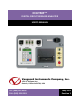

REV 3 DIGITMR USER’S MANUAL
4
NOTE
If a breaker test plan is used during testing, test results are compared with the
specifications in the test plan, and a “Pass” or “Fail” indicator is printed on the test
report based on the results of this comparison.
Breaker Initiate Capability
A built-in, solid-state, initiate device is used to operate a breaker from the
DigiTMR. Operational modes include Open, Close, Open-Close, Close-Open, and
Open-Close-Open. The multiple operations of Open-Close, Close-Open, and
Open-Close-Open can be initiated with a programmable delay time or by sensing the breaker’s
contact state.
The solid-state switching implemented in the initiate circuitry allows the DigiTMR to switch a
breaker’s AC or DC control circuit (30 A max, 250 Vac/dc). Each trip and close circuit is
protected by a 5-Ampere slow-blow fuse. An interlocking “ARM” switch also protects the
initiate circuit.
The DigiTMR not only plots the trip or close current waveforms, but also prints the steady-state
current readings of the trip and close coils during an operation. The DigiTMR features one, non-
contact, Hall-effect sensor with a range of 0-20 Amperes dc to 5Khz.
NOTES
• If the DigiTMR initiates the OPEN test or the CLOSE test in Quick-Shot Mode,
the test report will show the OPEN or CLOSE coil current readings and current
waveform.
• If the user operates the breaker in Quick-Shot mode using the external trigger,
no coil current reading or waveform will be recorded.
Trip/Close Current Monitoring
A built-in, hall-effect, current sensor records the trip and close coil current levels and duration.
The coil current waveform is graphically plotted on the DigiTMR’s built-in thermal printer. The
current reading is also printed on the tabulated test results report.
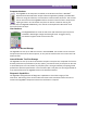
Built-in Thermal Printer
The DigiTMR features a built-in 4.5-inch wide thermal printer that can be
used to print the breaker’s contact analysis results in both tabular and
graphics formats. Please see section 2.5 for thermal paper ordering
information.