OPERATING INSTRUCTIONS for the DMOM-100 Series 2 DMOM-200 Series 2 10-100/200 Amperes True DC Digital Micro-Ohm Meters Vanguard Instruments Company 1520 S. Hellman Ave. Ontario, California 91761 TEL: (909) 923-9390 FAX: (909) 923-9391 January 2009 Rev.
DMOM-100/200 Series 2 Operating Procedures SAFETY SUMMARY NOTICE This manual applies to Models DMOM-100, and DMOM-200 Series 2. The operating procedures are virtually the same for all models. Any differences are clearly described in the step-by-step procedures. FOLLOW EXACT OPERATING PROCEDURES Any deviation from the procedures described in this operator’s manual may create one or more safety hazards, damage the DMOM, or cause errors in the test results. Vanguard Instruments Co., Inc.
DMOM-100/200 Series 2 Operating Procedures Table of Contents SAFETY SUMMARY.................................................................................................................... 2 1.0 INTRODUCTION .............................................................................................................. 6 1.1 Applicability ................................................................................................................... 6 1.2 General Description ...........................
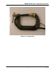
DMOM-100/200 Series 2 Operating Procedures Table of Figures Figure 1.0 Figure 2.0 Figure 3.0 Figure 4.0 Figure 5.0 Figure 6.0 Figure 7.0 Figure 8.0 Figure 9.0 Figure 10.0 Figure 11.0 Figure 12.0 Figure 13.0 Figure 14.0 Figure 15.0 Figure 16.0 Figure 17.0 Figure 18.0 Combined Current and Sense Leads ....................................................................... 7 DMOM-100/200 Sensing cable .............................................................................. 7 Hand Spike Sense Leads......
DMOM-100/200 Series 2 Operating Procedures List of Tables Table 1.0 Table 2.0 Table 3.0 Table 4.0 Table 5.0 Table 6.0 Table 7.0 Table 8.0 Table 9.0 Table 10.0 Table 11.0 Table 12.0 Table 13.0 DMOM-100 Series 2 Specifications......................................................................... 10 DMOM-200 Series 2 Specifications......................................................................... 11 Functional Description of DMOM-100 Series 2 Controls and Display ...................
DMOM-100/200 Series 2 Operating Procedures 1.0 INTRODUCTION 1.1 Applicability This manual applies to the Model DMOM-100 S2™ and Model DMOM-200 S2™ (hereafter, DMOM), made by Vanguard Instruments Company, Inc. 1.2 General Description The DMOM-100/200 Series 2 are the third generation micro-ohmmeters made by Vanguard Instruments Company. The DMOM-100/200 features microprocessor-controlled highly accurate measuring of very low resistances, ranging from 1 micro-ohm to 300 milli-ohms.
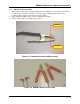
DMOM-100/200 Series 2 Operating Procedures 1.5 Optional Accessories 1. Heavy-duty welding-type C-clamps (Figure 5.0) are available as optional accessories. These C-clamps allow test lead connections to a wide variety of bushing sizes, bus bars, and conductors that require low-resistance test-lead contacts. 2. Light weight (#4 AWG) cables are also available upon request. 3. Custom cable lengths are available upon request. Current Jaw Voltage Jaw Figure 1.0 Combined Current and Sense Leads Figure 2.
DMOM-100/200 Series 2 Operating Procedures Figure 3.0 Hand Spike Sense Leads Figure 4.
DMOM-100/200 Series 2 Operating Procedures Figure 5.
DMOM-100/200 Series 2 Operating Procedures 2.0 DMOM SPECIFICATIONS 2.1 DMOM-100 Series 2 Specifications DMOM-100 specifications and leading particulars are listed in Table 1.0. Table 1.0 DMOM-100 Series 2 Specifications MODEL ...................... DMOM-100 Series 2 TYPE ............................. Special-Purpose Test Equipment, Portable, Low Resistance-Ohmmeter CONFIGURATION...... Third-generation (improved design, superseding original model) SIZE (inches) .............. 16.8” Wide by 12.
DMOM-100/200 Series 2 Operating Procedures 2.2 DMOM-200 Series 2 Specifications DMOM-200 specifications and leading particulars are listed in Table 2.0. Table 2.0 DMOM-200 Series 2 Specifications MODEL ...................... DMOM-200 Series 2 TYPE ............................. Special-Purpose Test Equipment, Portable, Low Resistance-Ohmmeter CONFIGURATION...... Third-generation (improved design, superseding original model) SIZE (inches) .............. 16.8 Wide by 12.6 High by 10.6 Deep (42.
DMOM-100/200 Series 2 Operating Procedures 3.0 CONTROL AND DISPLAY 3.1 DMOM-100 Series 2 Front Panel The DMOM-100 Series 2 controls and displays are shown in Figure 6.0, the control-panel illustration below. Pointing leader lines reference each item with an index number. Each index number is cross-referenced to a functional description in Table 3.0, which describes the function and purpose of each item on the control panel.
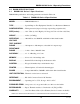
DMOM-100/200 Series 2 Operating Procedures Table 3.0 Functional Description of DMOM-100 Series 2 Controls and Display Figure 1 Index # Adjacent Panel Marking 1&9 (Wing Nut) 2 3 4 5 6 7 RS-232C 100-240 Vac, 8A, 50- 60 Hz No marking GROUND (Wing Nut) No marking No marking Functional Description Current lead connectors RS-232C interface port; 9-pin connector; female DB type. The data rate is set to 19,200 baud, 1 start bit, 8 data bits, and no parity bit; PIN ................
DMOM-100/200 Series 2 Operating Procedures 3.2 DMOM-200 Series 2 Front Panel The DMOM-200 Series 2 controls and displays are shown in Figure 7.0, the control-panel illustration below. Pointing leader lines reference each item with an index number. Each index number is cross-referenced to a functional description in Table 4.0, which describes the function and purpose of each item on the control panel.
DMOM-100/200 Series 2 Operating Procedures Table 4.0 Functional Description of DMOM-200 Series 2 Controls and Display Figure 1 Index # Adjacent Panel Marking 1&9 (Wing Nut) 2 3 4 5 6 7 RS-232C 100-240 Vac, 8A, 50- 60 Hz No marking GROUND (Wing Nut) No marking No marking Functional Description Current lead connectors RS-232C interface port; 9-pin connector; female DB type. The data rate is set to 19,200 baud, 1 start bit, 8 data bits, and no parity bit; PIN ................
DMOM-100/200 Series 2 Operating Procedures 4.0 DMOM IMPORTANT FEATURES 4.1 Operating Voltages The DMOM operates with voltages between 100-240Vac, 50/60Hz. 4.2 DMOM Serial Interface A built-in RS-232C port permits the DMOM to be interfaced with an IBM-compatible personal computer. An IBM PC-compatible software package supplied with each DMOM allows the user to retrieve test records stored in the DMOM’s memory. The software is compatible with Windows XP and Vista.
DMOM-100/200 Series 2 Operating Procedures 6.0 CABLE CONNECTION The DMOM is supplied with two 30-foot test cables with heavy-duty alligator clamps. Both current (#1 AWG) and sense leads are combined into one cable (Figure 1.0). A typical cable connection for the DMOM to a device under test (using the combined test lead) is shown in Figure 9.0 and Figure 11.0. Figure 8.0 and Figure 10.0 illustrate the connection using separate current and sense leads.
DMOM-100/200 Series 2 Operating Procedures Figure 10.0 DMOM-100/200 Connection Diagram 3 (Separate Leads) Figure 11.
DMOM-100/200 Series 2 Operating Procedures 7.0 OPERATING PROCEDURES 7.1 Step-by-Step Procedures Review Figure 14.0 before proceeding with the step-by-step procedures that follow. 7.2 Precautions Do not measure the resistance of inductive devices. This can generate unsafe high-voltage spikes (created by a collapsing magnetic field) if the test current is interrupted by detaching a test lead during a test.
DMOM-100/200 Series 2 Operating Procedures 1. ENTER ID 2. REVIEW RECORD 3. RESTORE RECORD 4. NEXT PAGE Figure 13.0 The SETUP Menu The SETUP MENU lists the following 4 user options. Item 1 (ENTER ID) is used to input identification information for each stored data record. Item 2 (REVIEW RECORD) is used to review stored records. Item 3 (RESTORE RECORD) is used to erase or restore test records or to print a directory of test records in stored memory.
DMOM-100/200 Series 2 Operating Procedures Figure 14.
DMOM-100/200 Series 2 Operating Procedures 7.6 Running a Normal Test Procedure The following procedure describes the steps to measure an unknown resistance. NOTE The red HIGH CURRENT PRESENT indicator will flash while the test current is applied to the resistance load. Table 5.0 STEP 5-1 5-2 5-3 Run Test Procedure (Measure an Unknown Resistance) ACTION DMOM DISPLAY Begin the Run Test procedure: From the START MENU, press key # 1. A menu of test options will appear, as shown at right.
DMOM-100/200 Series 2 Operating Procedures Table 5.0 Run Test Procedure (Measure an Unknown Resistance Continued) STEP 5-5 5-6 5-7 5-8 ACTION DMOM DISPLAY The SELECT RAMP TIME menu will appear. Push a key (1 through 4) to select a Ramp Time. For this example, push key # 1 to select 5 SEC (5 seconds). The display will show the selected test current, burn-in time, and ramp time. NOTE 5-second burn-in and ramp times were selected in this example.
DMOM-100/200 Series 2 Operating Procedures Table 5.0 Run Test Procedure (Measure an Unknown Resistance Continued) STEP 5-14 5-15 5-16 5-17 5-18 5-19 ACTION DMOM DISPLAY If the tested resistance measurement is to be stored in the test record buffer, press key # 1 (YES). The TEST SAVED message will be displayed. Press the ENTER key to continue. If the test is not to be stored in memory, press key # 2 (NO). The RUN ANOTHER TEST menu will appear. If another test is not needed, press key # 2 (NO).
DMOM-100/200 Series 2 Operating Procedures Table 5.0 Run Test Procedure (Measure an Unknown Resistance Continued) ITEM 5-20 5-21 ACTION DMOM DISPLAY Pressing key # 2 (NO) in response to the SAVE THIS TEST RECORD menu (see step 5-17) causes the ARE YOU SURE prompt (shown at right) to be displayed. To not save the record, press key # 1. To save the record, press key # 2.
DMOM-100/200 Series 2 Operating Procedures 7.7 Running an Automatic Test Procedure The Automatic Test Mode allows the user to initiate a test by applying the sense cable across the resistor load. This feature is handy when the user wants to take multiple resistance readings of the same load or of different loads in the same current path. The burn-in time for Automatic Test is set for 5 seconds. The resistance reading is stored in the DMOM’s working memory.
DMOM-100/200 Series 2 Operating Procedures Table 6.0 Run Test Procedure (Measure an Unknown Resistance Continued) STEP 6-4 6-5 6-6 6-7 6-8 6-9 ACTION DMOM DISPLAY The SELECT RAMP TIME menu will appear. Select a ramp time by pressing the corresponding key. For this example, press key # 1 to select a 5 SEC ramp time. The AUTOMATIC TEST start menu will display the selected test current, burn-in time, and ramp time. Press the START key to run the resistance measurement test.
DMOM-100/200 Series 2 Operating Procedures Table 6.0 Run Test Procedure (Measure an Unknown Resistance Continued) STEP 6-10 6-11 6-12 ACTION DMOM DISPLAY To save the record, press key # 1 (YES). If the test record is not to be saved, press key # 2 (NO) and go to step 6-12. NOTE The DMOM can store 96 readings per test record. A test record is saved in Flash EEPROM. A record number will be automatically assigned to the record by the DMOM (The Test record was assigned # 2 in this example).
DMOM-100/200 Series 2 Operating Procedures 7.8 Entering Test Record ID This procedure allows the user to enter the equipment identification data to the test record. Table 7.0 STEP 7-1 7-2 7-3 7-4 7-5 7-6 Enter Record ID Procedure (Company, Site, and Equipment Identification) ACTION DMOM DISPLAY Press key # 2 on the START MENU to go to the SETUP MENU shown at right. Note Setup options 2 thru 4 go to the following procedural tables: 2. REVIEW RECORD procedures in Table 8.0 3.
DMOM-100/200 Series 2 Operating Procedures Table 7.0 Enter Record ID Procedure (continued) STEP 7-7 7-8 7-9 7-10 ACTION DMOM DISPLAY Enter the test item’s MODEL using the alphanumeric keypad. Press the ENTER key to load the entered characters and advance to the SERIAL NUMBER input screen. Enter the test item’s SERIAL NUMBER using the alphanumeric keypad. Press the ENTER key to load the entered characters and advance to the KVA RATING input screen.
DMOM-100/200 Series 2 Operating Procedures 7.9 Reviewing a Record This procedure describes the steps for reviewing a test record residing in the DMOM’s working memory. The user can view the record on the LCD display or print the record on the thermal printer. The view feature is useful when the user wants to review a test record stored in the DMOM’s Flash EEPROM and there is no thermal paper for printing.
DMOM-100/200 Series 2 Operating Procedures Table 8.0 Review Record Procedure (continued) STEP ACTION 8-5 The “number of tests” display also shows the date and the time. Scroll through the test record (using the ∧ and ∨ keys to scroll). When the test record of interest appears, press the ENTER key to select it. 8-6 DMOM DISPLAY Pressing the ENTER key (from step 8-5) will list all test data, including test number, test current, burn-in time, and the measured resistance value.
DMOM-100/200 Series 2 Operating Procedures 7.10 Restoring a Record This procedure describes the steps to recall a test record stored in the DMOM’s Flash memory. Table 9.0 STEP 9-1 9-2 9-3 9-4 9-5 9-6 9-7 9-8 Restore Record Procedures ACTION DMOM DISPLAY On the START MENU, press key # 2 (SETUP) to display the SETUP MENU. On the SETUP MENU, press key # 3 (RESTORE RECORD) to display a menu of options (RESTORE RECORD, DIRECTORY, ERASE RECORD).
DMOM-100/200 Series 2 Operating Procedures Table 9.0 Restore record Procedures (continued) STEP 9-9 ACTION DMOM DISPLAY The RECORD RESTORED screen will be displayed. Press the ENTER key again to return to the REVIEW RECORD menu (resume the procedure at step 9-6) or press the STOP key to return to the START menu. RECORD RESTORED! This completes the Restore Record Procedure.
DMOM-100/200 Series 2 Operating Procedures 7.11 Printing the Test Record Directory This procedure describes the steps to print the DMOM’s Flash record directory. Table 10.0 Print Test Record Directory Procedures STEP 10-1 10-2 ACTION DMOM DISPLAY On the RESTORE RECORD display (step 92), press key # 2 (DIRECTORY) to go to the PRINT DIRECTORY menu. The PRINT DIRECTORY menu offers the choice to print either a FULL DIRECTORY or a SHORT DIRECTORY. Press Key # 1 (FULL DIRECTORY) or key # 2 (SHORT DIRECTORY).
DMOM-100/200 Series 2 Operating Procedures Figure 16.
DMOM-100/200 Series 2 Operating Procedures 7.12 Erasing Test Records This procedure describes the steps to delete a single test record or all the test records stored in the DMOM’s Flash EEPROM. Table 11.0 Erase Test Record Procedure STEP 11-1 ACTION DMOM DISPLAY On the RESTORE RECORD display (step 9-2), press key # 3 (ERASE RECORD) to display the ERASE RECORD menu of options (shown at right). 11-2 On the ERASE RECORD menu display, press key # 1 to erase a single record.
DMOM-100/200 Series 2 Operating Procedures 7.13 Computer Interface Mode A PC program is provided with each DMOM, which allows the user to download the test records stored in the DMOM’s Flash EEPROM to a PC. The user is required to put the DMOM in Computer Interface Mode to allow the PC running the program to access the test records stored in the DMOM’s Flash EEPROM. Test records can be stored on any media the PC is capable of handling.
DMOM-100/200 Series 2 Operating Procedures 7.14 Calibration Check This procedure describes the steps to perform the calibration check on the DMOM. Before conducting the calibration check, connect the current probes and sense probes to a piece of copper or aluminum bar, as shown in Figure 17.0 and Figure 18.0. Table 13.0 Calibration Check Procedure STEP 13-1 13-2 13-3 ACTION DMOM DISPLAY The calibration check is a functional verification self-test of the DMOM.
DMOM-100/200 Series 2 Operating Procedures Table 13.0 Calibration Check Procedure (Continued) STEP 13-8 ACTION DMOM DISPLAY Automatic. No operator action required. CAL CHECK COMPLETE PRESS ANY KEY 13-9 Press any key to end the CALIBRATION CHECK. The display will return to the START MENU. Figure 17.0 Calibration Connection (Separated Leads) Figure 18.
DMOM-100/200 Series 2 Operating Procedures APPENDIX A DMOM Troubleshooting Guide Item Symptom 1 The reading is incorrect. 2 “Cable Error” Message. Possible Problem 1. There is a poor connection at the test clips. 1. There is no test current going through the device under test. 2. There is a sensing cables problem. 41 Solution 1. Check the connections to ensure that the teeth of the voltage-sensing and current clips are firmly in contact with the device under test. 2.
DMOM-100/200 Series 2 Operating Procedures 1520 S. Hellman Ave, Ontario, CA 91761, USA Phone 909-923-9390 Fax 909-923-9391 Web site: http//www.vanguard-instruments.com DMOM-100/200 S2 Jan 2009 Copyright © 2009 by Vanguard Instruments Company, Inc.