
Owner`s manual


www.desatech.com
105604-01K 13
INSTALLATION
Continued
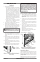
FIREBOX INSTALLATION USING
OPTIONAL ACCESSORY MANTELS
This rebox may be installed using the corner or
cabinet mantel with hearth base accessory against
a wall in your home. A trim kit is included with
each mantel accessory (see Accessories, page 18).
Follow the instructions included with mantels for
assembly and installation.
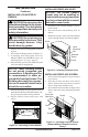
BUILT-IN FIREBOX INSTALLATION
Built-in installation of this rebox involves install-
ing rebox into a framed-in enclosure. This makes
the front of rebox ush with wall. If installing
a mantel above the rebox, but you must follow
the clearances shown in Figure 7, page 9. Follow
the instructions below to install the rebox in
this manner.
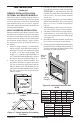
1.
Frame in rough opening. Use dimensions
shown in Figure 16 for the rough opening. If
installing in a corner, use dimensions shown
in Figure 17 for the rough opening. The
height is 33" (FB32CA and NLFB32C) or
34
1
/
4
"(FB32NCA and NLFB32NC), which is
the same as the wall opening in Figure 16.
2. Install gas piping to rebox location. This
installation includes an approved flexible
gas line (if allowed by local codes) after the
manual shutoff valve. The exible gas line
must be the last item installed on the gas pip-
ing. See Connecting to Gas Supply in log set
owner’s manual.
3. Carefully set rebox in front of rough open-
ing with back of rebox inside wall opening.
IMPORTANT: If installing Brass Trim Kit
GA6090, see instructions included with brass
trim accessory. You must install shoulder
screws now.
4. If using GA3750A blower accessory (Models
FB32CA and NLFB32C only), see Installing
Blower Accessory for built-in installation,
page 10.
5. Attach exible gas line to log set. See Connect-
ing to Gas Supply in log set owner’s manual.
6. Carefully insert rebox into rough opening.
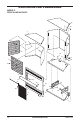
7. Attach rebox to wall studs using nails or
wood screws through holes in nailing ange
(see Figure 18).
8. Check all gas connections for leaks. See Checking
Gas Connections in log set owner’s manual.
9. If using optional GA6090 brass trim kit, install
the trim after nal nishing and/or painting of
wall. See instructions included with brass trim
accessory for attaching brass trim.
34
3
/
4
"
17
3
/
4
"
33" (FB32CA and
NLFB32CA)
34
1
/
4
" (FB32NCA and
NLFB32NCA)
Figure 16 - Rough Opening for Installing
in Wall
39
3
/8
"
27
7
/8
"
55
5
/8
"
34
3
/4
"
Figure 17 - Rough Opening for Installing
in Corner
Nailing
Flanges
Nails or
Wood
Screws
Figure 18 - Attaching Firebox to Wall
Studs
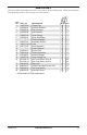
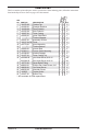
Model #
Front Width
Actual Actual
FB32CA 32
3
/
16
" 33" 34
3
/
8
" 34
3
/
4
"
NLFB32C 32
3
/
16
" 33" 34
3
/
8
" 34
3
/
4
"
FB32NCA 33
11
/
16
" 34
1
/
4
" 34
3
/
8
" 34
3
/
4
"
NLFB32NC 33
11
/
16
" 34
1
/
4
" 34
3
/
8
" 34
3
/
4
"
Model #
Actual
FB32CA 16
11
/
16
" 17
3
/
4
"
NLFB32C 16
11
/
16
" 17
3
/
4
"
FB32NCA 16
11
/
16
" 17
3
/
4
"
NLFB32NC 16
11
/
16
" 17
3
/
4
"