
Operation Manual

122
5
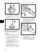
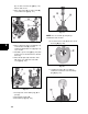
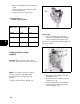
(D) and float bowl screw washer ([B] Fig.
109).
Fig. 109
2. Remove float hinge pin (A), carburetor
float (B) and float needle valve ([C] Fig.
110).
Fig. 110
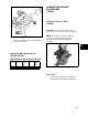
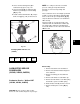
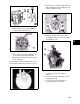
3. Remove main jet first ([A] Fig. 111) with a
carburetor jet screwdriver.
4. Remove carburetor emulsion tube ([B]
Fig. 111).
5. Remove rubber plug ([C] Fig. 111).
Fig. 111
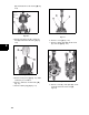
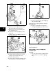
6. Remove screw ([A] Fig. 112).
7. Remove, throttle plate (B), throttle shaft
(C) and seal ([D] Fig. 112).
Fig. 112
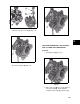
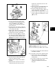
8. Remove screw (A), choke plate (B), choke
shaft (C) and choke shaft seal ([D]
Fig.113).