
Operation Manual

124
5
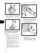
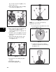
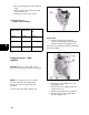
(C) on choke lever detents ([D] Fig. 117).
Rotate shaft closed.
3. Place choke plate (E) on choke shaft (B),
secure with screw ([F] Fig. 117).
Fig. 117
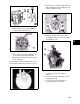
4. Place new throttle shaft seal ([A] Fig. 118)
on the throttle shaft (B). Insert in
carburetor with throttle lever ([C] Fig. 118)
set as shown.
5. Install idle speed screw ([D] Fig. 118) with
spring. Turn screw until it touches throttle
lever stop.
6. Place throttle plate (E) on throttle shaft
with holes over shaft and secure with
screw ([F] Fig. 118).
Fig. 118
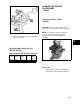
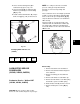
7. Insert tapered end of rubber plug (A) in
passage.
8. Install emulsion tube (B).
9. Install main jet ([C] Fig. 119).
Fig. 119
NOTE: For correct main jet and pilot jet
identification and selection.
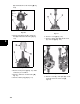
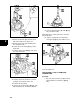
10. Insert the inlet needle (A) into the slot on
the float ([B] Fig. 120).
Fig. 120
11. Install float and needle assembly to
carburetor. Install and center float hinge
pin ([A] Fig. 121).
Fig. 121