
Operation Manual

36
2
Fig. 9
Fig. 10
Fig. 11
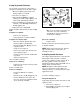
DC Shunt
When checking DC output on systems over 10
Amps, use a digital multimeter with the DC Shunt
([#19468] Fig.12) to avoid blowing a fuse in the
multimeter.
Fig. 12
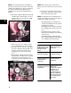
Tachometers
Tachometers are available from your Briggs &
Stratton source of supply. Order Tachometer
#19200 (A) or Digital Tachometer & Hourmeter
#19389 ([B] Fig. 13).
Fig. 13
ALTERNATOR OUTPUT TESTS
DC Only Alternator
The DC alternator provides current for charging a
12 volt battery. Current from the alternator is
unregulated and is rated at 3 amps. The output
rises from 2 amps at 2400 RPM to 3 amps at
3600 RPM.
Use an accurate tachometer and a tang bender
to temporarily adjust the engine speed to the
RPM specified in the test instructions before
testing alternator output.
Perform alternator tests in the following
sequence:
1. Test alternator output.
0 10 20 30
OF F
CO M
V
Ω
10A
FUS ED
Ω
V
∼
30 0m V
V
A
A
~
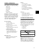
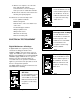
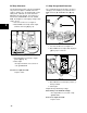
Diode Test
Insert the BLACK test lead
into the COM receptacle of
the multimeter. Insert the
RED test lead into the VΩ
receptacle. Set the rotary
switch to+))))). This setting
also signals continuity with
a continuous tone.
0 10 20 30
OF F
COM
V
Ω
10A
F USED
Ω
V
∼
30 0m V
V
A
A
~
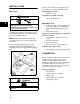
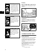
AC Amps
Insert the BLACK test lead
into the COM receptacle of
the multimeter. Insert the
RED test lead into the 10A
receptacle. Set the rotary
switch toA~.
0 10 20 30
OF F
CO M
V
Ω
10A
FUS ED
Ω
V
∼
30 0m V
V
A
A
~
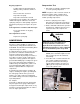
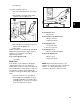
DC Amps under 10 Amps
Insert the BLACK test lead
into the COM receptacle of
the multimeter. Insert the
RED test lead into the 10A
receptacle. Set the rotary
switch to A===.