
Operation Manual

57
2
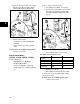
Test Key Switch & Solenoid
(138400, 185400, 235400, 245400)
Required Equipment:
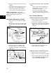
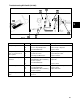
Set meter. See Figure 8.
1. Turn the key switch ON.
2. Check for continuity at the input side (A) of
the solenoid and ground ([B] Fig. 57).
Fig. 57
If continuity is present:
• Proceed to step 3.
If not:
• Replace key switch.
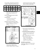
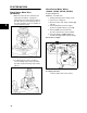
3. Check for continuity at the yellow terminal
(A) of the connector coming from the
switch with the key in the START position
and ground ([B] Fig. 58).
Fig. 58
If continuity is present:
• Proceed to step 4.
If not:
• Replace key switch.
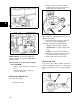
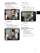
4. Reconnect the connector from the starter
switch.
5. Test for continuity at the output terminal
(A) of the solenoid with the key in the
START position and ground ([B] Fig. 59).
Fig. 59
If continuity is present:
• Replace starter.
If not:
• Replace solenoid.
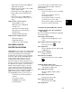
Check Starter Motor
(138400, 185400, 235400, 245400)
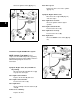
Required Equipment:
• Digital Multimeter #19464 (E).
• Tachometer #19200
• DC Shunt #19468 ([D] Fig. 57)
• A fully charged 12 volt battery Fig. 60.
1. Set multimeter to 300mv. See Figure 7.