VCBA VERSION 10.xx SOFTWARE MANUAL REV 2 TABLE OF CONTENTS CONVENTIONS USED IN THIS DOCUMENT ..................................................................................... 1 1.0 INTRODUCTION .................................................................................................................... 2 1.1 System Requirements ...................................................................................................... 2 2.0 SOFTWARE INSTALLATION ......................................
REV 2 VCBA VERSION 10.xx SOFTWARE MANUAL 5.4 Retrieving a Test Plan from a CB Analyzer ..................................................................... 63 5.5 Saving a Test Plan ........................................................................................................... 65 5.6 Saving a Test Plan from a Test Record ........................................................................... 65 5.7 Transferring a Test Plan to a CB Analyzer .................................................
VCBA VERSION 10.
REV 2 1.0 VCBA VERSION 10.xx SOFTWARE MANUAL INTRODUCTION The Vanguard Circuit Breaker Analyzer (VCBA) software is a Windows-based PC software application for use with Vanguard’s CT-6500, CT-7000, CT-7500, and DigiTMR circuit breaker analyzers. This software allows users to perform the following tasks: • • • • • • • 1.
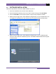
VCBA VERSION 10.xx SOFTWARE MANUAL 2.0 REV 2 SOFTWARE INSTALLATION Follow the steps below to install the VCBA software on your PC. 1. Insert the installation CD in the PC’s CD or DVD drive. 2. From the Windows Desktop, click on the “Start” button to bring up the Start Menu. 3. From the Start Menu, click on My Computer to open the My Computer window. 4. Double click (or single click in some Windows configurations) on your CD/DVD Drive icon to navigate the installation CD.
REV 2 VCBA VERSION 10.xx SOFTWARE MANUAL 6. Click on the “Next” button to continue. The following screen will be displayed showing the location on your hard drive where the software will be installed (C:\vanguard\VCBA): 7. You may choose a different installation location by clicking on the “Change…” button and then browsing to the location on your hard drive where you would like to install the software.
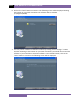
VCBA VERSION 10.xx SOFTWARE MANUAL REV 2 8. Click on the “Install” button. The InstallShield Wizard will copy files to your hard drive. The following screen will be displayed once the software has been successfully installed: 9. Click on the “Finish” button to close the InstallShield Wizard and complete the installation process. • The installation program will create two sub-folders, “shots” and “setup”, in the main installation folder.
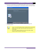
REV 2 3.0 VCBA VERSION 10.xx SOFTWARE MANUAL STARTING THE VCBA SOFTWARE During the installation process, a Vanguard program group will be created under the All Programs submenu in the Windows Start menu. To launch the VCBA software: 1. Click on the Windows “Start” menu button to open the Start Menu. 2. Click on the All Programs menu item. 3. Click on the Vanguard menu item. 4. Click on the VCBA menu item. 5. Click on the Launch vcba.exe menu item.
VCBA VERSION 10.
REV 2 3.2 VCBA VERSION 10.xx SOFTWARE MANUAL Enabling the Computer Interface The Computer Interface Mode allows you to retrieve test records and test plans from a CB analyzer and to transfer test plans to a CB analyzer. In this mode, tests can also be run on a CB analyzer from the PC. To enable the Computer Interface Mode: 1. Make sure the VCBA software is running on the PC. 2. Click on the Sys-Config menu and select System Setup… to configure the RS-232C communication port.
VCBA VERSION 10.xx SOFTWARE MANUAL REV 2 5. The following screen will be displayed: 1. ANALYSIS POINTS 2. MEASUREMENT UNITS 3. SAVE / RESTORE 4. NEXT PAGE Press the [4] key (NEXT PAGE). 6. The following screen will be displayed: 1. SHOT DESCRIPTION 2. COMPUTER ITF 3. SET CLOCK 4. SET PRINT MODE Press the [2] key (COMPUTER ITF). 7. The following screen will be displayed: COMPUTER ITF MODE “STOP” TO ABORT The CB analyzer is now ready to communicate with the VCBA software.
REV 2 3.3 VCBA VERSION 10.xx SOFTWARE MANUAL Application Setup You can customize the VCBA’s window colors and the font used to display data. You can also customize the colors used for the test record overlay graph (see section 4.11.4 for further information about overlaying test records). To customize the interface and overlay graph colors: 1. Click on the File menu and select Application Setup… The following window will be displayed: 2.
VCBA VERSION 10.xx SOFTWARE MANUAL 3.4 REV 2 System Setup To change the default system settings (such as the communication port, file location paths, etc): 1. From the File menu, click on System Config and then select System Setup… (Alternatively, if no test records or test plans are open, you can click on the Sys-Config menu and select System Setup…). The following window will be displayed: 2. Click on the “Port:” drop down list and select the PC COM: port that the CB analyzer is connected to. 3.
REV 2 4.0 VCBA VERSION 10.xx SOFTWARE MANUAL WORKING WITH TEST RECORDS The VCBA software can be used to retrieve test records from the CB analyzer or from the PC hard drive. Once a test record is retrieved, you can change the record header settings, print the test record, change velocity calculation points, change circuit breaker test parameters, and save the record to the hard drive. 4.1 Exploring the Test Records Directory You can access the default test records directory (please see section 3.
VCBA VERSION 10.xx SOFTWARE MANUAL REV 2 2. Put the CB analyzer in Computer Interface Mode. Please see section 3.2 for details. 3. From the Retrieve or File menu select Retrieve Test Records From Timer… 4. A window will appear listing a directory of all the test records stored in the CB analyzer’s memory: 5. You can select a shot to be retrieved by clicking on the shot number. The selected record will be highlighted.
REV 2 VCBA VERSION 10.xx SOFTWARE MANUAL 4.2.2. Retrieve Test Records to Directory The Retrieve Test Records to Directory… option from the Retrieve or File menu can be used to retrieve one or more records from a CB analyzer to a specific directory on the PC hard drive. 1. Make sure the VCBA software is running. Connect the CB analyzer to the PC via the RS232C port and turn on the power. 2. Put the CB analyzer in Computer Interface Mode. Please see section 3.2 for details. 3.
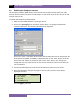
VCBA VERSION 10.xx SOFTWARE MANUAL 4.3 REV 2 Recalling Test Records From the PC Hard Drive Test records stored on the PC hard drive can be recalled using the steps below: 1. Click on the Recall Test menu (or click on the File menu and select Recall Test Record…). The following window will be displayed: • The top left section of the window displays the name of the directory where the test records are being retrieved from.
REV 2 VCBA VERSION 10.xx SOFTWARE MANUAL • You can also search for a particular record. You can start typing in the “Search” input field and it will actively highlight the first matching file name. For example, in the listing below, typing SAM in the “Search” field will highlight the “Sample Test 2” file name as shown below: 2. Click on the file name you would like to retrieve and click the “OK” button. The test record will be loaded and the tabulated test results will be displayed (please see section 4.
VCBA VERSION 10.xx SOFTWARE MANUAL 4.4 REV 2 Saving a Test Record 4.4.1. Saving a Test Record with its Original File Name 1. To save a test record with its original file name, click on the Save-Test menu and select Overwrite. 2. The test record will be saved with its original file name. 4.4.2. Saving a Test Record with a Different File Name 1. To save a test record with a different file name, click on the Save-Test menu and select Save As. The following window will be displayed: 2.
REV 2 4.5 VCBA VERSION 10.xx SOFTWARE MANUAL Copying a Test Record To copy a test record from one location on the PC hard drive to another location: 1. From the File menu, click on File Utilities and then select Copy Test Record… The following window will be displayed: 2. If the test record you would like to copy is not in the current directory, click on the “Path” button at the top of the window and browse to the directory containing the file.
VCBA VERSION 10.xx SOFTWARE MANUAL 4.6 REV 2 Renaming a Test Record To rename a test record stored on the PC hard drive: 1. From the File menu, click on File Utilities and then select Rename Test Record… The following window will be displayed: 2. If the test record you would like to rename is not in the current directory, click on the “Path” button at the top of the window and browse to the directory containing the file.
REV 2 4.7 VCBA VERSION 10.xx SOFTWARE MANUAL Deleting a Test Record To delete a test record from the PC hard drive: 1. From the File menu, click on File Utilities and then select Delete Test Record… The following window will be displayed: 2. If the test record you would like to delete is not in the current directory, click on the “Path” button at the top of the window and browse to the directory containing the file. Once you have located the test record to be deleted, click on the file name.
VCBA VERSION 10.xx SOFTWARE MANUAL 4.8 REV 2 Merging Test Records You can merge two test records to create a single test record. For example, you can combine two 6-channel timing shots to create a 12-channel timing shot. To merge two test records: 1. From the File menu, click on File Utilities and then select Merge Test Record… The following window will be displayed: 2. You can click on the “Path” button to browse to the directory containing the test records to be merged.
REV 2 4.9 VCBA VERSION 10.xx SOFTWARE MANUAL Exporting a Test Record in Microsoft® Excel® Format You can export a test record in Microsoft® Excel® format. To export a test record in Excel® format: 1. From the File menu, click on File Utilities and then select Export Test Record to Excel. The following window will be displayed: 2. If the test record you would like to export is not in the current directory, click on the “Path” button at the top of the window and browse to the directory containing the file.
VCBA VERSION 10.
REV 2 4.10 VCBA VERSION 10.xx SOFTWARE MANUAL Viewing and Working with Tabulated Test Results Once a test record has been retrieved (see sections 4.2 and 4.3 for instructions), the record details will be displayed as shown: The menus on the menu bar will also change to provide additional options relevant to working with a test record. You can edit the test record header information (such as Company, Station, etc.) by entering data in the corresponding fields at the top of the screen.
VCBA VERSION 10.xx SOFTWARE MANUAL REV 2 4.10.1. Viewing the Test Plan for a Test Record You can view the test plan for the test record by pressing the [Page Down] key on the keyboard. Below is an example of the test plan screen: You can return to the test record details by pressing the [Page Up] key. You may edit any of the test plan parameters by typing a new value in the input field. Press the [ENTER] or [TAB] key after entering a value.
REV 2 VCBA VERSION 10.xx SOFTWARE MANUAL NOTES 26 • When a test record is saved, the test plan is saved along with it. You may also save the test plan as a separate test plan file. Please see section 5.6 for further information. • The Contact Analysis values can also be changed from the menu system. From the File menu, click on Setup and then click on Contact Analysis. Then select the option you would like to edit.
VCBA VERSION 10.xx SOFTWARE MANUAL REV 2 4.10.2. Printing Tabulated Test Results To print the tabulated test results: 1. Retrieve the test record that you would like to print (See sections 4.2 and 4.3). 2. If you would like to print the test parameters with the tabulated test results: • From the File menu click on System Config and then click on System Setup… The following window will appear: Make sure the “Print Test Plan” checkbox is checked.
REV 2 VCBA VERSION 10.
VCBA VERSION 10.
REV 2 4.11 VCBA VERSION 10.xx SOFTWARE MANUAL Viewing and Working with Graphic Test Results To display graphic results of a timing record: 1. Retrieve the test record that you would like to view (See sections 4.2 and 4.3). 2. Click on the Graph/Results menu. The graphic results will be displayed as shown in Figure 4. Click on the Graph/Results menu again to return to the tabulated test results screen. Alternatively, you can press [CTRL]+[G] to toggle between the two views. 3.
VCBA VERSION 10.xx SOFTWARE MANUAL REV 2 4.11.1. Toggling the Display of the Velocity Curve To plot the velocity curve on the graphic test results: 1. From the File menu click on System Config and then click on System Setup… The following window will be displayed: If the “Plot Velocity Curve” checkbox is not already checked, click on the checkbox and a check mark will appear. Click on the “Save” button, and then click on the “OK” button.
REV 2 VCBA VERSION 10.xx SOFTWARE MANUAL If you do not want to display the velocity curve on the graphic test results: 1. From the File menu click on System Config and then click on System Setup… The following window will be displayed: If the “Plot Velocity Curve” checkbox is already checked, click on the checkbox to uncheck it. Click on the “Save” button, and then click on the “OK” button.
VCBA VERSION 10.xx SOFTWARE MANUAL REV 2 4.11.2. Customizing the Items Displayed on the Graphic Results Screen You can select which contact, travel, and voltage traces are displayed in the graphic test results. To select the items to be displayed: 1. Retrieve the test record that you would like to view (See sections 4.2 and 4.3). 2. Click on the Graph/Results menu to display the graphic test results. 3. Click on the Display menu and select Channel Display… The following window will be displayed: 4.
REV 2 VCBA VERSION 10.xx SOFTWARE MANUAL 4.11.3. Customizing the Graph Colors The foreground and background color of each Contact, Travel, Current, and Voltage trace can be customized. To change the trace colors: 1. Retrieve the test record that you would like to view (See sections 4.2 and 4.3). 2. Click on the Graph/Results menu to display the graphic test results 3. Click on the Display Menu and select Graph Color… The following window will be displayed: 4.
VCBA VERSION 10.xx SOFTWARE MANUAL REV 2 4.11.4. Overlaying Two Timing Shots You can graphically compare two timing shots on the screen by overlaying them. This is a very useful feature for viewing a circuit breaker’s operating condition. For example, test results from before and after breaker maintenance can be overlaid and compared. To graphically overlay two timing shots: 1. Click on the File menu and select Overlay Test Records… The following window will be displayed: 2.
REV 2 VCBA VERSION 10.xx SOFTWARE MANUAL 4. Click on the “OK” button and the graphic test results will be displayed as shown below: • Press the [Page Down] key to view the next page. Press the [Page Down] key to view the previous page. NOTES • You can customize the test record overlay graph colors. Please see section 3.3 for further information. 5. If you would like to print the overlay graphs, click on the Print menu and select Print Graphic.
VCBA VERSION 10.xx SOFTWARE MANUAL REV 2 4.11.5. Viewing a Graph Expansion You can expand a portion of the graphic test results for more accurate analysis. For example, if you want to view the graph from 0ms to 300ms: 1. Retrieve the test record that you would like to view (See sections 4.2 and 4.3). 2. Click on the Graph/Results menu to display the graphic test results. 3. Move the cursor over the graph area. A vertical hairline will appear at the cursor location.
REV 2 VCBA VERSION 10.xx SOFTWARE MANUAL 4. Hold down the left mouse button and drag the cursor to the right till the vertical hairline is at 300ms and the text at the bottom of the graph reads “T=300.00 ms” as shown below: 5. Release the mouse button and an expanded graph of the selected region will be displayed as shown below: 6. You can further expand the expansion graph by using the steps above. The maximum expansion that can be viewed is a range of 100ms.
VCBA VERSION 10.xx SOFTWARE MANUAL REV 2 7. Click anywhere on the graph area to view the entire graph again. • You can view an expansion of any of the graphic results pages. Simply press the [Page Up] and [Page Down] keys to view the desired graph page, and then follow the steps above to view an expansion. • You can also use the steps above to view an expansion of a graphic overlay screen (see section 4.11.
REV 2 VCBA VERSION 10.xx SOFTWARE MANUAL 4.11.6. Calculating the Average Velocity From the Graphic Test Results When viewing the graphic test results, you can view the velocity value at any point by moving the cursor over the point on the graph. The stroke and velocity value will be displayed at the top of the screen. You can also calculate the average velocity between two points by using the steps below: 1. Retrieve the test record that you would like to view (See sections 4.2 and 4.3). 2.
VCBA VERSION 10.xx SOFTWARE MANUAL REV 2 4. Hold down the RIGHT mouse button and drag the cursor to the second point on the travel curve: 5.
REV 2 VCBA VERSION 10.xx SOFTWARE MANUAL 4.11.7. Manually Overriding Contact Time/Resistor Contact Time or Contact Wipe You can override the calculated Contact Time, Resistor Time, or Contact Wipe readings in the tabulated test results. This is a useful feature for situations where a manual calculation is preferred.
VCBA VERSION 10.xx SOFTWARE MANUAL REV 2 2. Click on the Graph/Results menu to display the graphic test results. Then move the cursor to the preferred time that you would like to use as the override value. In this example, the cursor is positioned at 206.60 ms as shown below (note that the time at the cursor position will be displayed at the bottom of the graph as T = x.x ms): 3. Press the [F8] key.
REV 2 VCBA VERSION 10.xx SOFTWARE MANUAL 4. Click on the “Contact:” dropdown list to select the contact you would like to override the values for. For the example above, we would like to override the Close value for contact 2, so we will select 2 from the dropdown list. The values for contact 2 will be displayed as shown: 5. Click on the “Enable” checkbox next to each field that you would like to override with the value from the cursor position.
VCBA VERSION 10.xx SOFTWARE MANUAL REV 2 6. Click on the “OK” button. The override value will be inserted in the tabulated test results as shown: The above method works well for simple tests such as an OPEN or CLOSE test. For more complex situations such as a CLOSE-OPEN test with an insertion resistor, you can manually input the override values. To manually input the override values: 1. Retrieve the test record that you would like to view (See sections 4.2 and 4.3).
REV 2 VCBA VERSION 10.xx SOFTWARE MANUAL 4.11.8. Printing the Graphic Test Results To print the graphic test results: 1. While viewing the tabulated or graphics test results of a test record, click on the Print menu and select Print Graphic. 2. Select the printer you would like to print to and click on the “OK” button. All graphic test results pages will be printed. A typical graphic results printout is shown in Figure 5 below.
VCBA VERSION 10.xx SOFTWARE MANUAL 4.12 REV 2 Test Record Diagnostic Tools 4.12.1. Viewing Raw Shot Data The VCBA software has the ability to view the raw test record data. To view a dump of this data: 1. Retrieve the test record that you would like to view (See sections 4.2 and 4.3). 2. From the File menu, click on Diagnostics and then select Dump Shot Data… The following window will be displayed: 3. You can browse the raw shot data by clicking on the navigation buttons at the bottom of the window.
REV 2 VCBA VERSION 10.xx SOFTWARE MANUAL 4.12.2. Toggling the Resistor Flag When performing a timing test on a circuit breaker with an insertion resistor, it’s important to select the correct resistance value at the time the test is performed (please see section 6.0 for information on how to perform timing tests). If this value is not entered for some reason, incorrect test results may be obtained. However, this can be corrected using the VCBA software. To set the resistor value for a test record: 1.
VCBA VERSION 10.xx SOFTWARE MANUAL 5.0 REV 2 WORKING WITH TEST PLANS A circuit breaker test plan is comprised of all circuit-breaker performance specifications (stroke, velocity, and contact time). A test plan can be used to test a circuit breaker. When used with a test record, a Pass/Fail report is generated by comparing the actual performance of the breaker with the specifications in the stored test plan.
REV 2 VCBA VERSION 10.xx SOFTWARE MANUAL 4. This dialog box is used to define the Open Contact Analysis parameters. Enter the Contact Low, Contact High, Contact Delta, Resistor On Low, Resistor On High, and Resistor On Delta times (in milli-seconds) in each corresponding field. NOTES 50 • Contact Low is the fastest Open time of the circuit breaker main contacts. • Contact High is the slowest Open time of the circuit breaker main contacts.
VCBA VERSION 10.xx SOFTWARE MANUAL REV 2 After entering all the values, click on the “OK” button. The following window will be displayed: 5. This dialog box is used to define the Close Contact Analysis parameters. Enter the Contact Low, Contact High, Contact Delta, Resistor On Low, Resistor On High, and Resistor On Delta times (in milli-seconds) in each corresponding field.
REV 2 VCBA VERSION 10.xx SOFTWARE MANUAL NOTES • Contact Low is the fastest Close time of the circuit breaker main contacts. • Contact High is the slowest Close time of the circuit breaker main contacts. • Contact Delta, also known as Contact Spread, is the maximum time between the fastest and slowest contact time. • Resistor On Low is the fastest Close time of the circuit breaker insertion resistor contacts.
VCBA VERSION 10.xx SOFTWARE MANUAL REV 2 7. This dialog box is used to define the Contact and Resistor Open-Close Times or “Contact Dead Times” (in milli-seconds). Input the corresponding values for each field and click on the “OK” button. The following window will be displayed: 8. The VCBA’s tabulated report supports both English and Metric units of measure. Click on the English or Metric radio button to set the units of measure, and then click on the “OK” button.
REV 2 VCBA VERSION 10.xx SOFTWARE MANUAL NOTES • Stroke Low is the minimum distance of contact travel. • Stroke High is the maximum distance of contact travel. • Velocity Low is the minimum contact opening velocity. • Velocity High is the maximum contact opening velocity. • Overtravel Low should always be zero. • Overtravel High is the maximum contact distance travel above the Open position.
VCBA VERSION 10.xx SOFTWARE MANUAL NOTES REV 2 • Stroke Low is the minimum distance of contact travel. • Stroke High is the maximum distance of contact travel. • Velocity Low is the minimum contact Close velocity. • Velocity High is the maximum contact Close velocity. • Overtravel Low should always be zero. • Overtravel High is the maximum contact travel distance above the Close position.
REV 2 VCBA VERSION 10.xx SOFTWARE MANUAL For example, if you would like the Open Analysis Point #1 value to be 20% of stroke, click on the “Point #1” drop down list, select “Percent of Stroke” and input 20 in the input field below the drop down list as shown below: NOTES • Contact Point #1 is the distance from the fully closed position to the position when contact #1 opens.
VCBA VERSION 10.xx SOFTWARE MANUAL REV 2 12. This dialog box is used to set the Close Analysis Points. Set these values using the instructions in step 11 above. After you have set the values for both contact points, click on the “OK” button. The following window will be displayed: 13. This dialog box can be used to select a velocity calculation formula. To select a formula, click on the drop down list and select the preferred calculation method.
REV 2 VCBA VERSION 10.xx SOFTWARE MANUAL • Manual Stroke allows the user to define a scaling factor for the velocity calculation. If the stroke is measured as 5 inches by the travel transducer, using a manual stroke of 10 inches will scale the velocity calculations as a 2-to-1 ratio. • V = C / Time(AP1 to AP2): Velocity is calculated by a user-defined constant divided by the time (in milli-seconds) between analysis point #1 and analysis point #2.
VCBA VERSION 10.xx SOFTWARE MANUAL REV 2 Once you have set the trace colors per the instructions in section 4.11.3, click on the “OK” button. The following window will be displayed: 16. This dialog box allows you to select which contact, travel, and voltage traces are displayed in the graphic test results. Please refer to section 4.11.2 for further information. Once you have input the values per the instructions in section 4.11.2, click on the “OK” button. The following window will be displayed: 17.
REV 2 5.3 VCBA VERSION 10.xx SOFTWARE MANUAL Modifying an Existing Circuit Breaker Test Plan To modify an existing test plan: 1. Close any open test records or test plans. 2. Click on the Test-Plan menu and select Modify Test Plan… The following window will be displayed: 3. The timing plans in the current directory will be listed. You may click on the “Path” button at the top of the window to browse to another location on your computer.
VCBA VERSION 10.xx SOFTWARE MANUAL REV 2 6. If you do not want to save the changes to the test plan at this time, click on the “No” or “Cancel” button. If you would like to save the changes to the test plan, click on the “Yes” button. You will then be asked if you would like to overwrite the existing test plan file: If you would like to overwrite the current test plan file on the hard drive, click on the “Yes” button. If you would like to provide a different file name, click on the “No” button.
REV 2 VCBA VERSION 10.xx SOFTWARE MANUAL 8. You can make further changes to the timing plan by editing the tabulated values. Simply click on an input box and enter the new value, then press the [TAB] or [ENTER] key.
VCBA VERSION 10.xx SOFTWARE MANUAL 5.4 REV 2 Retrieving a Test Plan from a CB Analyzer To retrieve a test plan from a CB analyzer: 1. Make sure the VCBA software is running. Connect the CB analyzer to the PC via the RS232C port. 2. The CB analyzer should enter Computer Interface Mode. Please see section 3.2 for details. 3. Click on the File menu and select Retrieve Test Plan from Timer… The following window will be displayed: 4. Click on the test plan number that you would like to retrieve.
REV 2 VCBA VERSION 10.xx SOFTWARE MANUAL So if you would like the file name to be “TESTPLAN01.SET”, enter the word TESTPLAN in the “File” input field. 6. Click on the “OK” button to retrieve the selected test plans. The test plans will be stored in the default test plans directory. You can change the default test plan directory. Please see section 3.4 for further information.
VCBA VERSION 10.xx SOFTWARE MANUAL 5.5 REV 2 Saving a Test Plan To save an open test plan: 1. Click on the Setup menu and select Save Test Plan… 2. The test plan will be saved with the current file name. 5.6 Saving a Test Plan from a Test Record If you are viewing the tabulated test results of a test record, you can press the [Page Down] key to view the test plan portion of the test record. You can save the test plan by itself as a test plan file for future use.
REV 2 5.7 VCBA VERSION 10.xx SOFTWARE MANUAL Transferring a Test Plan to a CB Analyzer To transfer a test plan from the PC to a CB analyzer: 1. Make sure the VCBA software is running. Connect the CB analyzer to the PC via the RS232C port. 2. The CB analyzer should enter Computer Interface Mode. Please see section 3.2 for details. 3. Click on the File menu and select Transfer Test Plan to Timer… The following window will be displayed: 4.
VCBA VERSION 10.xx SOFTWARE MANUAL REV 2 5. This is a directory listing of the test plan locations in the CB analyzer’s Flash EEPROM and the test plans stored at each location. You can select an empty location to save to or you can click on a test plan name and replace the existing test plan at that location. Once you have selected a memory location to save to, click on the “OK” button. 6. You will hear some audible tones from the CB analyzer as the test plan is transferred to its Flash EEPROM.
REV 2 5.8 VCBA VERSION 10.xx SOFTWARE MANUAL Copying a Test Plan to a Different Location To copy a test plan from one location to another location: 1. From the File menu, click on Setup and then select Copy Test Plan… The following window will be displayed: 2. If the test plan you would like to copy is not listed in the current directory, click on the “Path” button at the top of the window and browse to the directory containing the file.
VCBA VERSION 10.xx SOFTWARE MANUAL 5.9 REV 2 Deleting a Test Plan To delete a test plan: 1. From the File menu, click on Setup and then select Delete Test Plan… The following window will be displayed: 2. If the test plan you would like to delete is not listed in the current directory, click on the “Path” button at the top of the window and browse to the directory containing the file. Once you have located the test plan file, click on the file name to select it.
REV 2 5.10 VCBA VERSION 10.xx SOFTWARE MANUAL Using a Test Plan for a Timing Test A test plan for a specific breaker can be used when performing a timing test (please see section 6.0 for instructions on how to perform timing tests). If a test plan is used, the Pass/Fail indicator will be displayed based on the settings in the test plan. To use a test plan with a timing test: 1. Close any open test records or test plans. 2.
VCBA VERSION 10.xx SOFTWARE MANUAL 5.11 REV 2 Printing a Test Plan If you currently have a test plan open and would like to print it: 1. Click on the File menu and select Print Tabulated. 2. Select the printer you would like to print to and click on the “OK” button. The tabulated test results will be printed. If you would like to print a test plan file that is not currently open: 1. From the File menu, click on Setup and then select Print Test Plan. The following window will be displayed: 2.
REV 2 6.0 VCBA VERSION 10.xx SOFTWARE MANUAL TIMING A CIRCUIT BREAKER USING THE VCBA SOFTWARE The VCBA software can be used to control a CB analyzer and run circuit breaker timing tests. The following tests are supported: OPEN, CLOSE, OPEN-CLOSE, CLOSE-OPEN, OPEN-CLOSEOPEN, and STATIC RESISTANCE. Also, a test plan for a specific breaker can be used with the test (please see section 5.10 for details).
VCBA VERSION 10.xx SOFTWARE MANUAL REV 2 6. From the “Insertion Resistor” radio box group, select the desired insertion resistance value. 7. From the “Trigger Type” radio box group, select the trigger type. 8. Click on the “OK” button. The following window will be displayed: 9. A 5-second timer will count down, and then the test will be initiated. A sequence of status messages will be displayed, and when the test is complete, the tabulated results will be displayed in the VCBA software main window.
REV 2 6.2 VCBA VERSION 10.xx SOFTWARE MANUAL Performing an OPEN-CLOSE test For an OPEN-CLOSE test, the CB analyzer will first open then close the circuit breaker after a preset time (in milli-seconds). To perform an OPEN-CLOSE test: 1. Make sure the VCBA software is running. Connect the CB analyzer to the PC via the RS232C port. 2. Put the CB analyzer in Computer Interface Mode. Please see section 3.2 for details. 3.
VCBA VERSION 10.xx SOFTWARE MANUAL REV 2 8. Click on the “OK” button. The following window will be displayed: 9. Type the delay time (in milli-seconds) in the input area and click on the “OK” button. The following window will be displayed: 10. A 5-second timer will count down, and then the test will be initiated. A sequence of status messages will be displayed, and when the test is complete, the tabulated results will be displayed in the VCBA software main window.
REV 2 6.3 VCBA VERSION 10.xx SOFTWARE MANUAL Performing a CLOSE-OPEN test For a CLOSE-OPEN test, the CB analyzer will first close then open the circuit breaker. To perform a CLOSE-OPEN test: 1. Make sure the VCBA software is running. Connect the CB analyzer to the PC via the RS232C port. 2. Put the CB analyzer in Computer Interface Mode. Please see section 3.2 for details. 3. Click on the File menu and select Time Breaker (alternatively you can click on the TimeCB menu from the Main menu bar).
VCBA VERSION 10.xx SOFTWARE MANUAL REV 2 8. Click on the “OK” button. The following window will be displayed: 9. You can select to initiate the trip command from this window. The following options are available: “Contact #1 Closed”: Trip breaker after detecting contact timing channel #1 is closed. “No Delay”: Trip breaker with no delay. Both Close and Trip coils are energized at the same time. “Delay Between Close to Open in mS”: Trip the breaker with a preset delay between the Close and Trip commands.
REV 2 6.4 VCBA VERSION 10.xx SOFTWARE MANUAL Performing an OPEN-CLOSE-OPEN test To perform an OPEN-CLOSE-OPEN test: 1. Make sure the VCBA software is running. Connect the CB analyzer to the PC via the RS232C port. 2. Put the CB analyzer in Computer Interface Mode. Please see section 3.2 for details. 3. Click on the File menu and select Time Breaker (alternatively you can click on the TimeCB menu from the Main menu bar). The following window will be displayed: 4.
VCBA VERSION 10.xx SOFTWARE MANUAL REV 2 8. Click on the “OK” button. The following window will be displayed: 9. Type the delay time (in milli-seconds) between the first Open command and the Close command. Click on the “OK” button. The following window will be displayed: 10. Type the delay time (in milli-seconds) between the Close command and the second Open command. The following window will be displayed: 11. A 5-second timer will count down, and then the test will be initiated.