
Installation manual


10
104409
UNVENTED NATURAL GAS FIREPLACE
DESA INTERNATIONAL
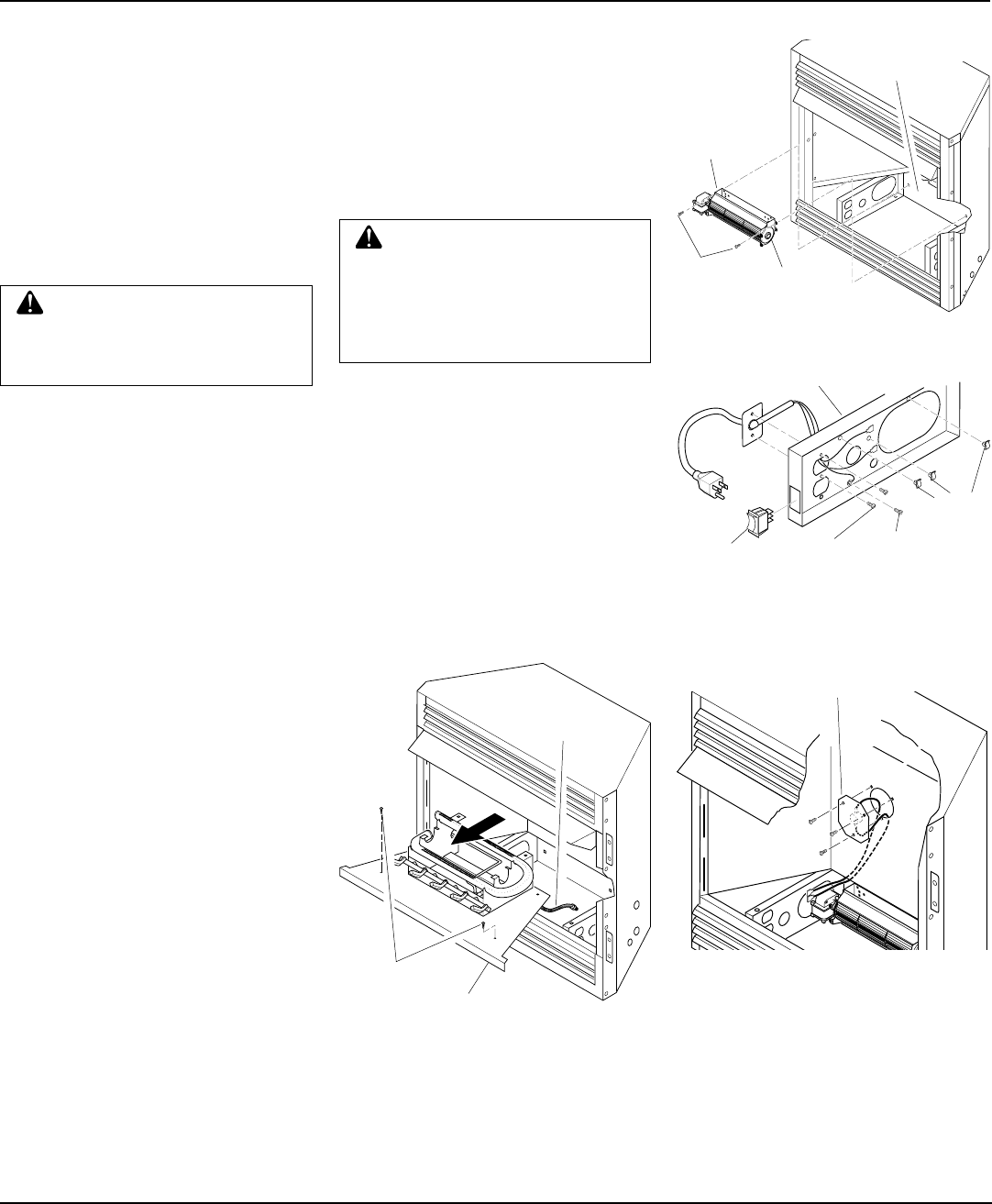
1. Remove screws that attach log base as-
sembly to fireplace (do not discard).
Carefully lift up log base assembly and
remove from fireplace, taking care to
pull flexible gas line through the ac-
cess holes (see Figure 13).
CAUTION: Do not pick up log
base assembly by burners. This
could damage burners. Only
handle base by grates.
2. Place the blower against lower rear wall
of firebox outer wrapper with the ex-
haust port directed upward. Align the
holes in top mounting tabs of blower
with holes in wall of wrapper (see Fig-
ure 14). Using two #8 screws provided,
mount blower and tighten screws
firmly.
3. Route terminals end of power cord
through large hole near top of left floor
support bracket. Make sure to pass the
cord from the outside (left side) towards
the center of firebox (see Figure 15).
4. Using two #6 screws provided attach
power cord mounting plate to the out-
side face of left floor support bracket.
Drive screws from inside (right side)
of floor support bracket. Attach the
plate so that the power cord is directed
towards rear of firebox (see Figure 15).
Tighten screws firmly.
5. Remove the three screws (do not dis-
card) and cover plate from center of
firebox wrapper rear wall. Discard this
cover plate.
6. Mount the supplied thermostatic switch
and cover assembly into firebox wrap-
per wall. Do this by feeding terminal
ends of wire harness into the hole. Al-
low wires to fall to bottom of firebox
cavity (see Figure 16).
7. Using three screws from step 5, attach
switch and cover assembly to firebox
wrapper rear wall. Tighten screws
firmly (see Figure 16).
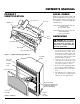
Figure 14 - Mounting Blower to Firebox
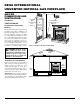
Figure 15 - Installing Power Cord,
Mounting Plate, and Selector switch
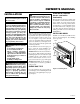
Figure 16 - Installing Switch and Cover
Assembly
Figure 13 - Removing Log Base from
Fireplace
8. Mount selector switch to front flange
of left floor support bracket. Align
graphics on switch upright and push
firmly to snap switch into rectangular
hole. Push the selector switch to the off
(middle) position (see Figure 15).
9.
Install three plastic wire clips provided
into floor support bracket (see Figure 15).
Secure by pushing clips firmly into holes.
WARNING: Failure to connect
all wires properly as indicated
may cause electrical short circuit
or personal injury. A qualified
electrician should check that all
connections are made properly.
10. Attach green ground wire ring termi-
nal to floor support bracket using #10
sheet metal grounding screw provided
(see Figure 15). Tighten screw firmly.
11. Attach all five remaining wiring termi-
nals to the appropriate switch or motor
terminal. Carefully note the correct
color coding (see Figures 17 and 19,
page 11). Push female wire terminals
fully onto male terminal.
12. Secure wires into the appropriate plas-
tic wire clips (see Figure 17, page 11).
INSTALLATION
Continued
Installing Optional GA3700T
Blower Accessory
Screws
Log Base
Flexible
Gas Line
Blower
#8 Screws
Exhaust Port
Lower Rear
Wall of Firebox
Outer Wrapper
#6 Screws
#10 Screw
Wire
Clips
Selector
Switch
Switch and
Cover
Assembly
AUTO
OFF
ON
3
2
1
Floor Support Bracket