
Electrical System Monitors

Electrical System Monitors
w w w w w w w w w w w w w w
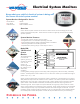
Know what your vehicle’s electrical system is doing with
the Vanner electrical system monitor.
System Monitors Designed for Use In:
Transit Buses Boats
Tour Buses Utility Vehicles
EMS Vehicles RVs and Motor Homes
w
w
w
w
ww
Experience the Power.
Overview
Vanner electrical system monitors sense several critical functions of a dual-voltage (24/12 Vdc)
vehicle or boat electrical system. These electrical monitors are typically used with Vanner battery
equalizer products.
System Monitor Features:
Continually monitors vehicle’s electrical system
Designed for dual 12 volt batteries operating at 24 Vdc
Detects battery high/low voltage and battery balance conditions
Takes the guesswork out of battery operation
Operates status/warning lamps, control relays or alarms
Model EM-
70D Electrical
System
Monitor
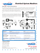
The model EM-70D
is wired to the
system’s ground, 12
volt DC, 24 volt DC
and +24 volt
ignition. By
monitoring the two
DC voltages, it can
detect fault
conditions,
including battery voltage high (over 30.0 volts), battery voltage low (under 24.0 volts), and battery
balance. A battery balance fault condition can occur when the 12 Vdc input is outside the range of
(24Vdc input 2) +/- 6%.
System monitoring takes place only when the ignition is switched on. The EM-70D has a 5-second
delay before the output terminal indicates an error condition. This feature prevents false indications
(blinking) from occurring when a “step load” change in system loads causes a transient on the DC
system. When a fault condition is detected, the EM-70D provides fault output signals that are
switched to ground. These outputs can operate external warning lamps, alarm buzzers or control
relays, and are rated for 375 milliamps (0.375 amps) DC. These outputs are short circuit protected
and are designed so they may be paralleled if less than three external lights are desired. It is also
possible to install momentary light test switches (or just one light test switch if three isolating diodes
are installed) which enable the operator to check the lamps to determine if they are functioning.
w
w
w
w
w
÷
+
24V
IGN.
SW.
POWER
ON
BATT.
LOW
BATT.
HIGH
BATT.
BALANCE
GROUND
+
12
VDC
+
24
VDC
POWER
ON
LED
BATT
BALANCE
BATT
HIGH
BATT
LOW
+
24
V
+
12
V
GND
+
24V
IGN.
SW.
System
Monitors
Model
EM70D
ELECTRICAL SYSTEM
MONITOR
QUICK CONNECTS
LAMP
OUTPUT
MONITOR
INPUT
w
w
w