
Owners Manual


Component Identification and
Description of Operation
IT SERIES Industrial True Sine Wave Inverter Owners Manual
17
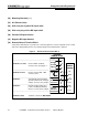
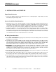
(32.1) Remote ON/OFF Switch Terminals 1, 2 and 3
The IT SERIES Inverter allows four styles of remote control wiring for customers who wish to
supply and install a remote control switch or switches.
Figure 7 Remote Control Switch Wiring Variations
Standard
No Remote Switch.
(Factory jumper connecting
terminals 1 and 2.)
Style One
Series Remote Switch
powered by Terminal 2.
(Factory jumper removed)
Style Two
Series Remote Switch
powered externally.
(Factory jumper removed.)
Style Three
Parallel Remote Switch
powered by Terminal 2.
(Factory jumper connecting
terminals 1 and 2.)
Style Four
Parallel Remote Switch
powered externally.
(Factory jumper connecting
terminals 1 and 2.)
(32.2) Remote Inverter Indicator Light (LED) Terminals 4 and 5
(See also item (10) Inverter Indicator Light
Use Terminals 4 and 5 to operate a customer supplied remote Inverter LED through a 470-ohm
resistor. The LED will light when the inverter is ON or in Load Demand Mode. A remote Inverter
LED does not blink when the inverter is in Load Demand Mode.
9 POS BLOCK
1
2
3
INTERNAL WIRING
INVERTER ON/OFF
+12/24VDC
9 POS BLOCK
INVERTER
1
2
3
INTERNAL WIRING
9 POS BLOCK
1
2
3
INTERNAL WIRING
9 POS BLOCK
1
2
3
INTERNAL WIRING
9 POS BLOCK
1
2
3
INTERNAL WIRING
SPST
REMOTE
SPST
REMOTE
JUMPER
JUMPER
JUMPER
+12/24VDC
1A FUSE
1A FUSE
SPST
REMOTE
SPST
REMOTE
+12/24VDC
INVERTER ON/OFF
+12/24VDC
INVERTER
INVERTER ON/OFF
+12/24VDC
INVERTER
INVERTER ON/OFF
+12/24VDC
INVERTER
INVERTER ON/OFF
+12/24VDC
INVERTER