INCORPORATED 4282 Reynolds Drive Hilliard Ohio, 43026 1(800) ACPOWER www.vanner.com RE SERIES Renewable Energy True Sine Wave ERTE R ON INV R RATO GENE UTILIT Y BATTE RY AC Power Inverter System TEMP ERAT URE CHAR GER AC Power Inverter/Charger OFF CAUTION - Risk of Electric Shock, Do Not Remove Cover. No User Serviceable Parts Inside. Refer Servicing To Qualified Service Personnel. CAUTION - Risk of Electric Shock, Both AC and DC Voltage Sources Are Terminated Inside This Equipment.
INCORPORATED Notes Copyright 2001 Vanner Inc. 4282 Reynolds Dr. Hilliard Ohio 43026 Phone: (614) 771-2718 FAX: 614-771-4904 www.vanner.
INCORPORATED Contents Contents 1 2 3 Introduction............................................................................................................. 1-1 Important Safety Instructions ................................................................................ 2-1 Safety Instructions .................................................................................................... 2-4 General Precautions .....................................................................................
INCORPORATED RE Installation Manual Factory Settings 24 VDC Only!! ....................................................................................2 Appendix D: Application Notes ..........................................................................................9 Application Notes..........................................................................................................9 Applicable Documents...........................................................................................
INCORPORATED Introduction 1 Introduction Thank you for purchasing a Vanner RE-4500 Renewable Energy Inverter System. We are confident that you will be satisfied with its performance and its many features. With proper installation and care, you can look forward to years of service from this high performance product. “RE-4500” stands for Renewable Energy 4500 Watt, Inverter System.
INCORPORATED RE Installation Manual Save these instructions! Please note your model and serial number here for future reference. Model No. Serial No. Date of Installation This document describes the operation, technical specifications and installation procedures for the RE-4500 Inverter/Charger System. If you require additional information please contact your dealer or contact Vanner at 1-800-AC POWER (1-800227-6937). 1-2 Copyright 2001 Vanner Inc. 4282 Reynolds Dr.
INCORPORATED Important Safety Instructions 2 WARNING: Important Safety Instructions Before you install and use your RE-SERIES AC Power Inverter, read and save these safety instructions! This manual contains important safety and operating instructions for the Vanner Incorporated RE-4500 Power Inverter that shall be followed during installation and maintenance of the inverter as prescribed by Underwriters Laboratories (UL).
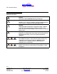
INCORPORATED RE Installation Manual NOTE: In order to reduce the risk of damage to personnel or equipment, please read all instructions in this manual, particularly warnings noted by the following symbols. These symbols are used to note procedures that if not closely followed could lead to loss of life or damage to equipment or property due to electrocution.
INCORPORATED Important Safety Instructions L1 N Phase 1 This symbol denotes that this termination is used for the upper phase of a 240 Vrms 3 wire system consisting of Phase 1 (Black wire), Neutral (White wire), and Phase 2 (Red wire). Neutral This symbol denotes that this termination is used for the middle wire of a 240 Vrms 3 wire system consisting of Phase 1 (Black wire), Neutral (White wire), and Phase 2 (Red wire).
INCORPORATED RE Installation Manual Safety Instructions Caution Read owners manual BEFORE wiring or powering up. Caution DO NOT cover or obstruct ventilation openings. DO NOT mount in a zero-clearance compartment. Overheating may result. Warning Under high ambient temperature / high-power-output conditions some parts of the inverter may become hot enough to cause burns. The unit should be installed so that it is not to be contacted by personnel.
INCORPORATED Important Safety Instructions General Precautions Do not expose the inverter/charger to direct water spray, rain, or snow. To reduce the risk of a fire hazard, do not cover or obstruct the ventilation openings. Do not install the inverter in a zero clearance compartment. This may result in overheating and/or diminished performance. To avoid the risk of fire, electrical shock, or injury to persons, do not use attachments not recommended or sold by Vanner Incorporated.
INCORPORATED RE Installation Manual Always use service disconnects to break the circuit before attempting any kind of servicing of the RE-4500. DO NOT attempt to service the unit while still actively connected to a power source of any kind. Explosive Gas Precautions This equipment contains components, which tend to produce arcs or sparks. To prevent fire or explosion, do not install in compartments containing batteries or flammable materials, or in locations that require ignition protected equipment.
INCORPORATED Important Safety Instructions Before attempting any sort of wiring for the DC supply to the Inverter, turn off the DC disconnect associated with the Batteries. For Safety, ALWAYS check the operation of the disconnect with a voltmeter! In addition to the lethal current associated with the batteries, care must be taken to avoid any potential problems or explosions from the batteries.
INCORPORATED Installation And Start-Up 3 Installation And Start-Up This section contains 2 versions of the installation procedures: one for the experienced installer which is designed for installers familiar with the system, and a second for a new installer who may be unfamiliar with the Inverter/Charger system. Please refer to the appropriate Installation procedure for your level of expertise.
INCORPORATED RE Installation Manual Locate a secure, dry, flat vertical surface large enough to mount the inverter. The location should be as close to the battery as possible, usually within six feet, but not in the same compartment and should provide adequate ventilation while the inverter is operating. The location must be clean, dry, free of dripping water, snow, or other moisture contamination. Warning Allow 12 inches minimum clearance below the RE-4500 for the Fan to provide adequate cooling.
INCORPORATED Installation And Start-Up F 1 Figure 3-1: RE-4500 System Connections Generator Generator Contacts GND Start +24VDC Run 8 Conductor Control Cable DC Cables AC Power Inverter System AC LOADS L1 Neutral Bar Solar Array Junction Box To Load L2 U INCORPORATED DC SOURCES PV Arrays BATTERIES & Other Sources DC LOADS AC Control Module INCORPORATED Battery Bank A DC INTERRUPTION / POWER DISTRIBUTION AC DISCONNECT L2 L1 B A B RE-4500 RE-DCM MULTI-MODE ALTERNATIVE ENERGY INVERTE
INCORPORATED RE Installation Manual F 3 Figure 3-3: Inverter AC Raceway Connections 26 27 Left Right L1 N GND L2 AC OUT L1 N GND L2 AC IN 29 28 Bottom Warning Class 1 Wiring Methods Are To Be Used For Field Wiring Connections To Terminals Of A Class 2 Circuit. It Is Also Extremely Important To Observe A Physical Separation Between Class 1 And Class 2 Circuits. Be Sure To Route Class 1 And Class 2 Wiring Through Separate Knockouts And Conduits.
INCORPORATED Installation And Start-Up been written for your protection and their requirements should be followed. (15) Battery Temperature Sensor Monitor Port This RJ11 Port enables battery bank temperature monitoring with the optional Vanner Battery Temperature Sensor (Vanner Part Number RE-BTS1). This sensor is used for optimizing battery charging efficiency, extending battery life, and battery fault monitoring.
INCORPORATED RE Installation Manual (19) Relay D Contacts These terminals are available to the user from the RE-4500 and can be used for several programmable functions. These three Terminals are designated as Normally Open, Common, and Normally Closed. This relay’s factory default use is undefined at this time. (20) Control Relay Ground Terminal This is a ground pin for the auxiliary output voltage from the main DC bus.
INCORPORATED Installation And Start-Up Warning This terminal is grounded to the Inverter Chassis. Check Polarity Carefully! Attaching the Positive supply to this terminal can result in loss of life, damage to the system, the batteries, and voiding of Warranty. Check your terminations carefully! (24) Serial Control Connection This RJ-11 jack is for serial communication between the RE4500 and another computer/controller.
INCORPORATED RE Installation Manual (28) Chassis Ground Connect to compression fitting terminal using 10 gauge wire minimum. (29) Exhaust Fan This port is used to exhaust the cooling air from the unit. Controls All controls are located on the front of the unit. This includes the ON/OFF Switch found on the front of the unit. The optional Inverter Charger Controller, RE-ICC/LCD is also available for remote command of the RE-4500.
INCORPORATED Installation And Start-Up Testing Procedure This section is designed to be utilized by a experienced installer or electrical contractor who has prior experience with installation of the RE-4500 and is to provide an installation procedure checklist to insure that the Inverter has been installed properly. Perform the following checks before continuing: 1. Mount the inverter properly mounted with sufficient ventilation. 2.
INCORPORATED RE Installation Manual 8. Verify that there is no voltage present on the inverter AC output terminals (between L1 and Neutral). 9. Connect a 120 Volt 75 watt trouble light (or other suitable load) to the inverter AC output (between L1 and neutral) and turn on inverter via the front panel switch. 10. Refer to the description of operation of the indicator lights, in the RE-4500 Owners Manual. 11. If the inverter is not operating as described, see Trouble Shooting Procedures of this document.
INCORPORATED Installation And Start-Up DC Wiring Considerations • A DC fuse is REQUIRED to properly protect the inverter in case the battery cables are connected backward (reverse polarity). Use a Vanner Part Number 04095 Very Fast Acting 400 amp fuse. • The wiring of your inverter installation should conform to the National Electric Code (NEC) and any other state or local codes in effect at the time of installation.
INCORPORATED RE Installation Manual F 5 Figure 3-5: DC Wiring Diagram DC Control and Distribution Wiring Junction Box 100A Charge Controller #1 100A Charge Controller #2 DC Conduit Solar Array AC Power Inverter System Battery Bank 300A U 1A GFDI INCORPORATED RE-4500 MULTI-MODE ALTERNATIVE ENERGY INVERTER L1 N GND N GND L2 L1 L2 AC OUT AC IN Warning It is important to disconnect ALL DC sources to avoid electric shock! DC Voltage is extremely dangerous and contact with DC Currents can l
INCORPORATED Installation And Start-Up required, cut a slot to connect the two holes to prevent heating of the ferrous metal. 4. If passing through any sort of holes, make certain that strain reliefs are used to avoid cutting or abrasion of insulation over time. 5. Proper DC cable size is critical for the performance and safe operation of the inverter system. It is required by Vanner that the installer use 4/0 AWG wire to minimize losses to less than ½ volt over the length of the cable.
INCORPORATED RE Installation Manual DC Wiring Installation Procedure The DC wiring raceway is located at the top of the inverter (Figure 3-6). The DC cables may enter the inverter through the left or the right side openings to the raceway (Figure 3-6). Conduit knockouts are provided. Bolts and spring washers are provided for connecting 5/16” diameter ring terminals to the DC Input Contacts. Optional compression lugs (Vanner part no. D08241) are available for cables sizes up to 250 MCM.
INCORPORATED Installation And Start-Up F 7 Figure 3-7: Inverter DC Raceway Terminations - 23 22 + Left 24 (48VDC or 24VDC) Right + 21 20 16 17 18 19 25 15 NC C NC C NO NO +VDC C NC C NC Gnd NO NO (48VDC or 24VDC) A B C D Front 1. Select a location for the inverter. An ideal location is close to the battery; protected from weather and moisture; and well ventilated.
INCORPORATED RE Installation Manual 6. Insert the DC cables through the appropriate knockout and into the DC wiring raceway. 7. Torque the DC cable mounting bolts to 105 inch pounds. Re-torque after 30 days. 8. Inspect the DC cable compartment to be sure no copper wire fragments are present after tightening cables. 9. Route the negative DC cable to the DC source disconnect (or Vanner DCM). Verify cable polarity before proceeding.
INCORPORATED Installation And Start-Up 17. Verify that the inverter will turn ON but do not leave the inverter connected to the DC source(s) at this time (turn off the DC disconnect). Final DC connections will be made after all control and AC output installation issues have been inspected. AC Utility/Load Wiring Installation Procedure Warning Before proceeding with the AC wiring, verify that the inverter is OFF and that the inverter is NOT connected to the battery.
INCORPORATED RE Installation Manual Warning This Diagram is for informational purposes ONLY!!! Please refer to National and Local Electrical Wiring codes to insure compliance and safety! Warning External Output Overcurrent Protection Must Be Provided By Using A 40 A Circuit Breaker (Maximum).
INCORPORATED Installation And Start-Up F 9 Figure 3-9: AC Wiring Diagram Start AC Power Inverter System GND +24VDC Generator Start Contacts Generator U Transfer Switch INCORPORATED RE-4500 MULTI-MODE ALTERNATIVE ENERGY INVERTER L1 N GND N GND L2 L1 L2 AC OUT L1 AC IN Utility Meter L1 N L2 L2 From Utility N Inverter Bypass Inverter Bypass Main AC Disconnect To Load AC Control / Distribution Wiring F 10 Figure 3-10: Inverter AC Raceway Terminations 26 27 Left Right L1 N GND
INCORPORATED RE Installation Manual Warning It is important to disconnect ALL AC sources to avoid electric shock! AC Voltage is extremely dangerous and contact with AC Currents can lead to injury, damage to property, and death! Use the AC disconnect to insure that ALL potentials are disabled. Use a lockout to insure that voltages are not inadvertently reconnected. Note It should be noted that the RE-4500 does not require the rewiring of Multiwire branch circuits since it is a true 3 wire 240 Vrms output.
INCORPORATED Installation And Start-Up 9. Connect L1, N, L2 and ground to the appropriate terminals in the terminal strip and torque each of the AC terminal screws to 15 inch pounds. Re-torque after 30 days. 10. Use the Chassis Ground compression fitting (28) to ground the chassis using 10 gauge wire. Connect the chassis ground wire to the compression fitting and torque the bolt to 75 inch pounds. Re-torque after 30 days. 11. Verify AC wiring installation. Verify that all connections are tight.
INCORPORATED RE Installation Manual Start-up and Test Procedure After the inverter has been properly mounted with sufficient ventilation, verify the following: 1. DC cables have been connected to the inverter and to the DC Disconnect 2. DC cable polarity is correct. 3. The DC Disconnect is still in the OFF position (no voltage present at output of the Disconnect) 4. AC Disconnect is in the OFF position (no voltage present on the output of the Disconnect). 5. AC wiring has been completed 6.
INCORPORATED Installation And Start-Up 7. Refer to the description of operation of the indicator lights, in Indicator Lights on page 3-16. 8. If the inverter is not operating as described, see Trouble Shooting Procedures on page 5-2. 3-31 Copyright 2001 Vanner Inc. 4282 Reynolds Dr. Hilliard Ohio 43026 Phone: (614) 771-2718 FAX: 614-771-4904 www.vanner.
INCORPORATED System Setup 4 System Setup System Control and Setup This section describes the Control of the RE-4500. The controls set consists of an On/Off switch and the Inverter/Charger Controller. If more information is needed, please refer to the RE-4500 Owners Manual. On/Off Switch The On/Off switch located on the front panel, turns on and off the internal logic power supply. This switch also when placed in the “Off” position resets the system.
INCORPORATED RE Installation Manual changed by a Vanner Certified Installer or by Authorized Factory Personnel. There are no field adjustable Trip Points. All of these Trip points are password protected to avoid incorrect entries. Warning Wrong settings can damage the unit, and lead to personal injury or death, and voiding of the manufacturers warranty.
INCORPORATED System Setup Display and Key Functions The features and functions of the RE-ICC are: (1) Display Used to display Menu selections, Data Entry Fields, Status Messages (2) Top Left Key Selection of menu items or scrolling up through the menu (3) Bottom Left Key Selecting a displayed item, increasing (Incrementing) display items, Selecting an “ON” or “YES” function (4) ESC Key ESC (Escape) key is used to “back up” to the next higher menu and/or to cancel new data being entered.
INCORPORATED RE Installation Manual LCD Contrast Control An additional feature for the LCD (Liquid Crystal Display) version of the RE-ICC is a contrast control. By holding down the ESC key and pressing either the Top Right Key (to make the display lighter) or the Bottom Right Key (to make the display darker), the contrast can be adjusted. Note: This adjustment for the contrast only works with the LCD type display! The VFD (Vacuum Fluorescent Display) is unaffected by this control.
INCORPORATED System Setup Help Menu Gives Version level, Help, and Index menus. Alarm Menu Displays status messages for the RE4500, automatically scrolls through the listing of active alarms. See Alarm Listing in Appendix C: Settings.
INCORPORATED RE Installation Manual F 13 Figure 4-3: Main Menu Startup Display TurboRemote XA88974-A 2 seconds Main Menu MENU ESC SETTINGS Settings Menu Display Menu SETTINGS ALARMS ADVANCED HELP To HELP MENU To ADVANCED Root MENU Example Alarm List Depends on number of Alarms Inverter ON off Charger on OFF Grid Interact on OFF Menu Battery on OFF Menu Miscellaneous Stacking on Menu Menu Menu To INVERTER MENU To CHARGER MENU To Grid Interact MENU To Battery MENU To Miscellaneou
INCORPORATED System Setup 1. Press the Top Right Key next to the ↓ symbol. This will move you to the next menu item. The Display will change to Charger on OFF 2. Keep pressing the Top Right Key next to the ↓ symbol. You will see that each time you press the key that the screen will advance down the list in Figure 4-3. Note: If you hold the ↓ key down the menu items will scroll DOWN rapidly. 3. Try pressing the Top Left Key next to the ↑ symbol.
INCORPORATED RE Installation Manual 5. If you are not at the “Inverter on OFF” screen, go to it now and press the “MENU” button. You will now be at a new screen. Small ON Inverter off You are now at the first item in the INVERTER Menu. The Inverter Menu structure is shown in Figure 4-4. As you can see, you have a lot of options of where to go from here! 6. Press the ESC key. This will take you back to the SETTINGS Menu. The Display should look like the following: Inverter on OFF 7.
INCORPORATED System Setup F 14 Figure 4-4 Inverter Menu INVERTER MENUS Inverter on INVERTER MENU ON Small Inverter off Small YES Inverter no OFF MENU MENU VOLTAGE Limits MENU + + Inv. Output 240.0 Vrms Max Inv. Currnt 18.75 Arms - Small Inverter MENU + Small Inv Strt 75 Watts - + Small Inv Stop 80 Watts - + Small Inv Tail 5 Seconds - + Small Inv Ramp 4 Cycles - + Small Inv Delta 1 Seconds - MENU SURGE MENU Upper Volts #1 + 264.0 Vrms - MENU + + Max Inv. Srge 1 28.
INCORPORATED RE Installation Manual F 15 Figure 4-5: Advanced Menu Advanced MENU SETTINGS ALARMS ADVANCED HELP HELP ADVANCED REMOTE SETTINGS MENU COMMUNICATIONS MENU CALIBRATION MENU CUSTOMIZATION MENU + Password? 7734 - REMOTE SETTINGS COMMUNICATIONS CALIBRATION CUSTOMIZATION PASSWORD DEBUG CONTENTS INDEX ABOUT INDEX MENU (TBD) CONTENTS MENU (TBD) ABOUT MENU DEBUG MENU ↓” symbol. This 9. Press the Bottom Right key next to the “↓ will take you to the screen shown below.
INCORPORATED System Setup 11. Next, press the Top Left key next to “Password”. This will take you into the Password Menu. The screen shown below should now appear. + Password? 7734 - This Password system is used for allowing (or not allowing) changes to RE parameters (for more information on the PASSWORD function, refer to Changing the Password Settings on page 4-13. 12. Press the Bottom right button near the “–“ symbol. You will see the 7734 change to 7733 and continue going down.
INCORPORATED RE Installation Manual In the EQUALIZATION Menu there is a screen that looks like the following: Equalize Type DC Voltage The “!” and “"” symbols mean that there are additional selections that may be made for this menu item. In this case (as shown in the CHARGER Menu in Appendix B: RE-ICC Menus the selections are DC POWER, DC CURRENT, and DC VOLTAGE. Since entry “DC VOLTAGE” is at the bottom of the list, the Lower Left Key should be used to move up through the list.
INCORPORATED System Setup Changing the Password Settings This Section will show you how to change the password. Access to the Inverter/Charger Controller has three levels of access. • User – (7734) This level of access allows viewing of all the menu items and some limited adjustment of parameters, but no adjustment to the more advanced parameters. Changes are limited to the following list.
INCORPORATED RE Installation Manual Display Menu This Menu is accessed by pressing the “Menu” button when at the Main Menu. This will bring up the menu shown in Figure 4-1: Display Menu. This menu can be used to display status of voltages, currents, power, temperature, or many other monitored status items associated with the RE-4500. The “ESC” key will take you back to the Main menu.
INCORPORATED System Setup Charger Setup The following sections will give an example in how to set up the Charger menus of the inverter. The first example is for a 3 step charging cycle, and the second is for a 7 step charging cycle (The factory setting). It is recommended that the user be familiar with the operation of the ICC (Inverter/Charger Controller) before attempting the Charger Setup examples shown below. Please refer to the RE Owners Manual for more information on the ICC.
INCORPORATED RE Installation Manual Figure 4-6 shows the Charger Menu for reference. F 16 Figure 4-6: Charger Menu Charger MENU RE24-4500 24V System Charging Steps Menu Charger on Generator Menu OFF + MENU + MENU Charging Steps 7 Steps Relay Board YES + Grid Good Delay + 90 Secs - MENU Grid Good Menu MENU - Soft Start Rmp 10 Seconds - Selections DC POWER DC CURRENT DC VOLTAGE Chrg Stg Type DC Current Chrg Stg Sttng + 0.0Adc - Watts Adc Vdc Selections Upper Freq #1 65.
INCORPORATED System Setup Charger MENU RE48-4500 48V System Charging Steps Menu Charger on Generator Menu OFF + MENU + MENU Charging Steps 7 Steps Relay Board YES + MENU Chrg Stg Sttng + 0.0Adc - + Lower Freq #1 55.00 Hz - Trigger Settng + 44.00 Vdc NO + Upper Freq #2 70.00 Hz - Chrg Stg Tmout + 0.00 Hours - - + Lower Freq #2 40.00 Hz - APM Limit 30.
INCORPORATED RE Installation Manual NOTE It should be noted that the RE-4500 is shipped with the Factory Settings for flooded-cell, lead acid type batteries. Warning Please refer to the manufacturers data sheets for setting up the appropriate set points for voltage and current for your charging system. Failure to do so could cause damage to your batteries and/or reduction in their life. Wrong settings could also cause other damage to the system and voiding of your manufacturer’s warranty.
INCORPORATED System Setup g. And last, set "Charge Timeout" to "0.00 Hours." Press the Top Right Key to take you back to “Charge Step #”. This charge step is a placeholder where nothing really happens to the batteries until their voltage falls and they truly do need a charge. At that point, the inverter charges the batteries at 0 Adc until the battery voltage falls below 22.0 Vdc, and then goes on to the next charging step. 3. Perform the second set of charging steps: a. Set "Charge Step #" to 2.
INCORPORATED RE Installation Manual e. Choose the "End Chrg Type" to be "
INCORPORATED System Setup deplete to before charging starts. Press the Top Right Key. g. And last, the "Charge Timeout" is "0.00 Hours." Press the Top Right Key to take you back to “Charge Step #”. This first charge step is kind of a placeholder where nothing really happens to the batteries until their voltage falls off and they truly do need a charge. That is, the inverter charges the batteries at 0 Adc until the battery voltage falls below 22.
INCORPORATED RE Installation Manual d. The "Charge Setting" is "28.40 Vdc" (56.8 VDC for the RE48-4500) the same as the end point of the last stage. Press the Top Right Key. e. The "Trigger Type" is "
INCORPORATED System Setup a. Set "Charge Step #" to 5. (The fifth charging stage) Press the Top Right Key. b. The "Charge Stage " is "EQUL" standing for equalization. Press the Top Right Key. c. The "Charge Type" is "DC VOLTAGE." Press the Top Right Key. d. The "Charge Setting" is "31.00 Vdc." (62 Vdc for the RE48-4500) Press the Top Right Key. e. The "Trigger Type" is "
INCORPORATED RE Installation Manual the batteries increases to greater than 50 amps (25 Adc for the RE48-4500) or until an hour has gone by, after which the inverter will then go on to the next charging stage. Note: The current when charging probably won't rise so the only effective trigger is the timeout. This means the batteries will be left on float for at least an hour before going on to the next stage. 7. Perform the seventh set of charging steps: a. Use the remote to set "Charge Step #" to 7.
INCORPORATED Preventive Maintenance and Trouble Shooting Procedures 5 Preventive Maintenance and Trouble Shooting Procedures There are no user serviceable components inside the inverter. If the inverter requires service, refer to the Vanner Incorporated or other qualified service personnel. Preventive Maintenance For continued reliability and safety, a monthly maintenance program should be implemented to include the following: 1.
INCORPORATED RE Installation Manual Trouble Shooting Procedures The following are the most common questions heard by Vanner service professionals. If your situation does not apply to the following categories, please contact your local Vanner Inc. Service Center or the Vanner Inc. Customer Service Department: 1-800-AC-POWER (1-800-227-6937). Please have your model and serial number available when consulting customer service. Preliminary Checks 1. Indicator Light status. 2. Inverter ON/OFF Switch position.
INCORPORATED Preventive Maintenance and Trouble Shooting Procedures Problem Symptoms and Troubleshooting Checks If you have this problem: Do this: Inverter Indicator Light does not turn ON. Inverter Indicator Light is ON but the AC load will not operate. Verify DC voltage at the inverter. Check and reset GFCI receptacle or circuit breakers. Verify AC wiring. Try a different load such as a trouble light. Check battery connections and condition. Recharge battery if voltage is less than 22.
INCORPORATED Appendix A: Warranty Appendix A: Warranty NORTH AMERICAN LIMITED WARRANTY Vanner Inc., doing business as The Vanner Inc., referred to herein as Vanner, warrants that this product is free from defects in materials and workmanship for a period of two (2) years from date of installation or two and one half (2 1/2) years from date of manufacture, whichever is less if and only if the following requirements are complied with: 1.
INCORPORATED RE Installation Manual Vanner reserves the right to repair, replace, or allow credit for any material returned under this warranty. Any damage caused by the customer will be charged or deducted from the allowance. All warranty work will be performed at Vanner’s factory, by authorized Vanner distributors, by Vanner installers/technicians, or a Vanner authorized repair facility utilizing a valid Warranty Authorization Number (WAN) prior to repair.
INCORPORATED Appendix B: RE-ICC Menus Appendix B: RE-ICC Menus MENU ESC SETTINGS ALARMS Settings Menu Help Menu Remote Settings Menu Surge Menu Communications Menu Voltage Limits Menu Alarms Listing ESC Advanced Menu Inverter Menu ESC HELP ESC ESC ADVANCED Display Menu About Menu Contents Menu Index Menu Small Inverter Menu (TBD) (TBD) Calibration Menu Customization Menu Fan Menu Charger Menu Charge Stages Menu Generator Menu Equalization Menu Password Menu Debug Menu Grid Intera
INCORPORATED RE Installation Manual Startup Display TurboRemote XA88974-A 2 seconds Main Menu MENU ESC SETTINGS Settings Menu Display Menu SETTINGS ALARMS ADVANCED HELP To HELP MENU To ADVANCED Root MENU Example Alarm List Depends on number of Alarms Inverter ON off Charger on OFF Grid Interact on OFF Menu Battery on OFF Menu Miscellaneous Stacking on Menu Menu Menu To INVERTER MENU To CHARGER MENU To Grid Interact MENU To Battery MENU To Miscellaneous MENU OFF Menu To Stacki
INCORPORATED Appendix B: RE-ICC Menus Display Menu INV L1 VLT-AMP 2555 VA GRID L2-to-N 119.8 Vrms INVERTER TIME 10:10:31 INV L1 PWR-FCT 88% GRD L2 CURRENT 18.70 Arms INVERTER DATE 1/ 1/ 0 INVRTR L2-to-N 119.8 Vrms GRID L2 POWER -2250 Watts INV L2 CURRENT 18.70 Arms GRD L2 VLT-AMP 2240 VA BATTERY STATUS LOW - OFF INVRTR L2 POWR -2250 Watts GRD L2 PWR-FCT -99% BATTERY VOLTS 13.27 Vdc INV L2 VLT-AMP 2240 VA GRID FREQUENCY 60.00 Hz BATTERY PWR 0 Watts INV L2 PWR-FCT -99% PLL LOCK ERROR 0.
INCORPORATED RE Installation Manual INVERTER MENUS Inverter on INVERTER MENU ON Small Inverter off Small YES Inverter no OFF MENU MENU VOLTAGE Limits MENU + Inv. Output 240.0 Vrms - + Max Inv. Currnt 18.75 Arms - Small Inverter MENU + Small Inv Strt 75 Watts - + Small Inv Stop 80 Watts - + Small Inv Tail 5 Seconds - + Small Inv Ramp 4 Cycles - + Small Inv Delta 1 Seconds - MENU SURGE MENU MENU + + Max Inv. Srge 1 28.13 Arms - Max Inv. Srge 2 + 37.
INCORPORATED Appendix B: RE-ICC Menus Charger MENU RE24-4500 24V System Charging Steps Menu Charger on Generator Menu OFF Selections Charge Stage # + MENU + MENU Charging Steps 7 Steps Relay Board YES Generator Strt ON + - + + Lower Freq #1 55.00 Hz - Trigger Settng + 22.0 0 Vdc NO + Upper Freq #2 70.0 0 Hz - Chrg Stg Tmout + 0.0 0 Hours - - + Lower Freq #2 40.0 0 Hz - MENU MENU Watts Adc Vdc Selections Trigger Type
INCORPORATED RE Installation Manual Charger MENU RE48-4500 48V System Charging Steps Menu Charger on Generator Menu OFF + MENU + MENU Charging Steps 7 Steps Relay Board YES + + Soft Start Rmp 1 0 Seconds Grid Good Menu MENU DC POWER DC CURRENT DC VOLTAGE Chrg Stg Sttng + 0.0Adc - + + Lower Freq #1 55.00 Hz - Trigger Settng + 44.0 0 Vdc NO + Upper Freq #2 70.0 0 Hz - Chrg Stg Tmout + 0.0 0 Hours - - + Lower Freq #2 40.
INCORPORATED Appendix B: RE-ICC Menus Grid Interact Menus Grid Interact on OFF MENU + Load Support 10.0 0 Arms - Grid Frq Sttngs Grid Vlt Sttngs Grid Freq. MENU MENU Grid Voltage MENU MENU + UL 1741 Delay 30 1 Secs - + Upper Freq #1 60.2 5 Hz - + Upper Volts #1 264. 0 Vrms - + Lower Freq #1 59.7 5 Hz - + Lower Volts #1 211. 8 Vrms - + Upper Freq #2 60.5 0 Hz - + Upper Volts #2 328. 0 Vrms - + Lower Freq #2 59.3 0 Hz - + Lower Volts #2 119.
INCORPORATED RE Installation Manual Battery MENU RE24-4500 24 Volt System Battery MENU + Low Batt Warn. 22.0 0 Vdc - + LowBat ShutDn 21.0 0 Vdc - + HighBat Shutdn 31.0 0 Vdc - Battery Temp. Menu Batt Temp Comp on OFF MENU + Batt Bad Delay 1 3 Secs - High Batt Shut + 60. 0 ° C - + Batt Good Delay 1 Secs - Low Batt Shut + 0. 0°C - + Batt Temp Strt 25. 0°C - + Batt Temp Coef -5. 00mV/°C/Cl - # of Cells + 1 2 - B-8 Copyright 2001 Vanner Inc. 4282 Reynolds Dr.
INCORPORATED Appendix B: RE-ICC Menus Battery MENU RE48-4500 48 Volt System Battery MENU + Low Batt Warn. 44.0 0 Vdc - + LowBat ShutDn 42.0 0 Vdc - + HighBat Shutdn 61.0 0 Vdc - Battery Temp. Menu Batt Temp Comp on OFF MENU + Batt Bad Delay 1 3 Secs - High Batt Shut + 60. 0 ° C - + Batt Good Delay 1 Secs - Low Batt Shut + 0. 0°C - + Batt Temp Strt 25. 0°C - + Batt Temp Coef -5. 00mV/°C/Cl - # of Cells + 1 2 - B-9 Copyright 2001 Vanner Inc. 4282 Reynolds Dr.
INCORPORATED RE Installation Manual Miscellaneous MENU Miscellaneous MENU Auto Restart ON off MENU Output Feedbck ON off + + Auto Restart 5 Mins - Shutdown Temp. 70. 0 °C - Display Board YES no Reset EEPROM yes NO Inverter Communications MENU Inverter Addr. + 1- + Xmit Timeout 1 Secs - + Recv Timeout 0 Secs Retries + 5- B-10 Copyright 2001 Vanner Inc. 4282 Reynolds Dr. Hilliard Ohio 43026 Phone: (614) 771-2718 FAX: 614-771-4904 www.vanner.
INCORPORATED Appendix B: RE-ICC Menus Stacking MENU Stacking on OFF MENU Supervisor on OFF + Invertr 1 Addr. 3 - + Invertr 2 Addr. 2 - + Phase Angle 0.0 0 ° - Time and Date MENU Time and Date MENU + Inverter Time 10:10:3 1 - + Inverter Date 1/ 1/2000 - B-11 Copyright 2001 Vanner Inc. 4282 Reynolds Dr. Hilliard Ohio 43026 Phone: (614) 771-2718 FAX: 614-771-4904 www.vanner.
INCORPORATED RE Installation Manual Advanced MENU SETTINGS ALARMS ADVANCED HELP HELP ADVANCED REMOTE SETTINGS MENU COMMUNICATIONS MENU CALIBRATION MENU CUSTOMIZATION MENU + Password? 773 4 - CONTENTS INDEX REMOTE SETTINGS COMMUNICATIONS CALIBRATION CUSTOMIZATION PASSWORD DEBUG ABOUT INDEX MENU (TBD) CONTENTS MENU (TBD) ABOUT MENU DEBUG MENU B-12 Copyright 2001 Vanner Inc. 4282 Reynolds Dr. Hilliard Ohio 43026 Phone: (614) 771-2718 FAX: 614-771-4904 www.vanner.
INCORPORATED Appendix B: RE-ICC Menus ABOUT MENU CONTENTS INDEX ABOUT ABOUT TurboRemote XA88974-A VANNER, INC. (c) 2000 All Rights Reserved www.vanner.com PH:614-771-2718 FX:614-771-4904 Geoff, Kirby Tim, Lucreasey, Bill, Yelena Steve & Jeff RE-4500 SW PART # A88838A B-13 Copyright 2001 Vanner Inc. 4282 Reynolds Dr. Hilliard Ohio 43026 Phone: (614) 771-2718 FAX: 614-771-4904 www.vanner.
INCORPORATED RE Installation Manual REMOTE SETTINGS MENU REMOTE SETTINGS REMOTE SETTINGS COMMUNICATIONS COMMUNICATIONS + Display Blank 60 Minutes Alrm Pll Delta + 60 Seconds Scan Invrtrs yes NO + Inverter Addr. 1 - + Remote Addr. 0 - B-14 Copyright 2001 Vanner Inc. 4282 Reynolds Dr. Hilliard Ohio 43026 Phone: (614) 771-2718 FAX: 614-771-4904 www.vanner.
INCORPORATED Appendix B: RE-ICC Menus CALIBRATION MENU CALIBRATION CALIBRATION CUSTOMIZATION Frequency Adj.
INCORPORATED RE Installation Manual CUSTOMIZATION MENU CUSTOMIZATION + Phaselock -2.0 0 ° + Lg Xfrmr Ratio 18.93 2 - + Sm Xfrmr Ratio 15.95 8 - + Invertr Derate -154. 8 mA/°C - CALIBRATION CUSTOMIZATION - FAN MENU MENU + Large Xfrmr 0 Cnts - Small Xfrmr + 0 Cnts - + + + Grid + Feedbck 1000 0 Cnts Lg Xfrmr Ddbnd 512 0 Cnts Sm Xfrmr Ddbnd 512 0 Cnts - Maximum Modul. + 3085 7 Cnts - + Offset -77.0 0 ° - + Gain -1240 0 ° /W- + Max. Fan Volts 12.2 0 Vdc - + Min. Fan Volts 6.
INCORPORATED Appendix B: RE-ICC Menus PASSWORD AND DEBUG MENU + Password? 773 4 PASSWORD - DEBUG PASSWORD DEBUG EEPROM Rd/Wrt + Address: 0EEPROM Rd/Wrt + (@ 0): 0- B-17 Copyright 2001 Vanner Inc. 4282 Reynolds Dr. Hilliard Ohio 43026 Phone: (614) 771-2718 FAX: 614-771-4904 www.vanner.
INCORPORATED Appendix C: Settings Appendix C: Settings Alarm Listing Alarm Display Description BATTERY LOW BATT. TOO HIGH BATT. TOO LOW CURRENT LIMIT BROWNED OUT Battery Low Warning Battery High Shutdown Battery Low Shutdown At the Inverter current limit Shutdown because the inverter output voltage has been too low for too long Power stage shutdown Transformer overheated The power stage overheated The batteries overheated.
INCORPORATED L1-N OUT BROWN L2-N OUT BROWN L1 IN SURGING L2 IN SURGING L1 APM LIMIT L2 APM LIMIT L1 in current regulation mode (brown-out) L2 in current regulation mode (brown-out) L1 Coming up on APM limit L2 Coming up on APM limit L1 is at APM Limit L2 is at APM Limit Factory Settings 24 VDC Only!! SETTING NAME EEPROM Version FACTORY VALUE DEFAULT VALUE value value Battery Settings SETTING NAME Number of Cells High Battery Shutdown Low Battery Shutdown Low Battery Warning Battery Offset Battery Ga
INCORPORATED Appendix C: Settings Frequency Settings SETTING NAME FACTORY VALUE DEFAULT VALUE 1st Frequency Bad Delay (UL1741) 2nd Frequency Bad Delay (UL1741) Displayed Frequency Adjust Frequency Good Delay Generator Upper Capture Frequency Generator Lower Capture Frequency Generator Upper Lock Frequency Generator Upper Lock Frequency Stacking Phase Angle Phaselock Detect Angle Frequency Adjust GridTie Frequency Adjust (not used) Grid Interactive Upper Capture Frequency Grid Interactive Lower Capture
INCORPORATED Communications Settings SETTING NAME FACTORY VALUE DEFAULT VALUE 3 2 1 1S 1S 5 3 2 1 1S 1S 5 Inverter #1 Address Inverter #2 Address Inverter Address Inverter Transmit Timeout Inverter Receive Timeout Inverter Number of Retries Systems Settings SETTING NAME FACTORY VALUE Automatic Restart Timeout ON/OFF Controls: 5 Minutes Subordinate Stacking Grid Interactive Charger Inverter Automatic Restart Small Inverter Load Demand Generator Start Battery Temperature Compensation Output Feedbac
INCORPORATED Appendix C: Settings Systems Settings SETTING NAME APM Limit APM Surge Limit 1 APM Surge Limit 2 APM Surge Limit 3 Grid L1 Current Offset Grid L2 Current Offset Grid L1-to-N Offset Grid L2-to-N Offset Inverter L1 Current Offset Inverter L2 Current Offset Inverter L1-to-N Offset Inverter L2-to-N Offset Grid L1 Current Gain Grid L2 Current Gain Grid L1-to-N Gain Grid L2-to-N Gain Inverter L1 Current Gain Inverter L2 Current Gain Inverter L1-to-N Gain Inverter L2-to-N Gain Upper Voltage Limit #1
INCORPORATED Inverting Settings SETTING NAME FACTORY VALUE DEFAULT VALUE Inverter Output Voltage Large Transformer Output Ohms Tap Transformer Output Ohms (not used) Small Transformer Output Ohms Maximum Inverter Current Maximum Inverter Surge Current #1 Maximum Inverter Surge Current #2 Maximum Inverter Surge Current #3 Small Inverter / Load Demand Ramp Up/Down Small Inverter / Load Demand Exit Small Inverter / Load Demand Start Small Inverter / Load Demand Tail Small Inverter / Load Demand Delta 240.
INCORPORATED Appendix C: Settings Charging Settings SETTING NAME FACTORY VALUE DEFAULT VALUE "STRT" DC POWER < DC VOLTAGE -300 W 22.00 Vdc 0.00 Hours "STRT" DC CURRENT < DC VOLTAGE 0.0 Adc 22.00 Vdc 0.00 Hours "BLKC" DC CURRENT >= DC VOLTAGE 100.0 Adc 28.40 Vdc 24.00 Hours "BLKC" DC CURRENT >= DC VOLTAGE 100.0 Adc 28.40 Vdc 24.00 Hours "BLKV" DC VOLTAGE < DC CURRENT 28.4 Vdc 55.0 Adc 1 Hour "BLKV" DC VOLTAGE < DC CURRENT 28.4 Vdc 55.0 Adc 1 Hour "ABRB" DC CURRENT >= DC VOLTAGE 50.0 Adc 30.
INCORPORATED Charge Stage #7 Charge Stage Name Charge Stage Type Trigger Type Charge Stage Setting Trigger Setting Charge Stage Timeout Charge Stage #8 Charge Stage Name Charge Stage Type Trigger Type Charge Stage Setting Trigger Setting Charge Stage Timeout Number of Charging Stages Charging Soft Start Ramping Time "END " DC VOLTAGE >= DC VOLTAGE 26.40 Vdc 50.0 Adc 0.00 Hours "END " DC VOLTAGE >= DC VOLTAGE 26.40 Vdc 50.0 Adc 0.00 Hours "EQUL" DC VOLTAGE < DC CURRENT 31.00 Vdc 10.00 Adc 0.
INCORPORATED Appendix D: Application Notes Appendix D: Application Notes Application Notes Please refer to the Vanner Incorporated Web site for Application notes at: http://www.vanner.com. Applicable Documents National Electric Code 1999 NEC Article 690 UL-1741 IEEE-929 1 G.A. Kern, R.H.Bonn, J. Ginn, S. Gonzalez Results of Sandia National Laboratories Grid-Tied Inverter Testing, July 1998 D-9 Copyright 2001 Vanner Inc. 4282 Reynolds Dr.
INCORPORATED Vanner Inc. 4282 Reynolds Drive Hilliard, Ohio 43026 1-800-AC POWER (1-800-227-6937) Tel: 614-771-2718 Fax: 614-771-4904 www.vanner.com e-mail: pwrsales@vanner.com Manual Part Number D910157-A Printed in USA Copyright 2001 Vanner Inc. 4282 Reynolds Dr. Hilliard Ohio 43026 Phone: (614) 771-2718 FAX: 614-771-4904 www.vanner.