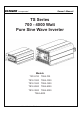
VANNER Owner’s Manual Incorporated TS Series 700 - 4000 Watt Pure Sine Wave Inverter Models TS12-700 TS24-700 TS12-1000 TS24-1000 TS12-1500 TS24-1500 TS12-2000 TS24-2000 TS12-3000 TS24-3000 TS24-4000 700~4000 Watt TS Series Inverter Owner’s Manual -1-
VANNER Owner’s Manual Incorporated Table of Contents 1. 2. SAFETY INSTRUCTIONS 4 1-1. General Safety Precautions 4 1-2. Other Safety Notes 5 FUNCTIONAL CHARACTERISTICS INTRODUCTION 6 2-1. System 6 2-2. Block Diagram 6 2-3. Electrical Specification 7 2-3-1. TS12-700, TS24-700 Specification ................................................ 7 2-3-2. TS12-1000, TS24-1000 Specification ............................................ 8 2-3-3. TS12-1500, TS24-1500 Specification .....................
VANNER 4. Incorporated OPERATION Owner’s Manual 24 4-1. Connection the DC cable 24 4-2. Connecting the input power 25 4-3. Connecting the loads 25 4-4. Switch ON Inverter 25 4-5.
VANNER Incorporated Owner’s Manual 1. Safety Instructions 1-1. General Safety Precautions Warning! Before using the Inverter, read the safety instructions. Do not expose the inverter to rain, snow, spray or dust. To reduce the risk of fire hazard, do not cover or obstruct the ventilation openings and do not install the inverter in a zero-clearance compartment.
VANNER Incorporated Owner’s Manual 1-2. Other Safety Notes Upon receipt, examine the carton box for damage. If you have found any damage on the carton box please notify Vanner. Do not operate near water or in excessive humidity. Do not open or disassemble the inverter, and warranty may be voided. The DC side connections should be firm and tight. Grounding: Reliable grounding should be maintained. Do not drop a metal tool on the battery.
VANNER Incorporated Owner’s Manual 2. Functional Characteristics Introduction 2-1.
VANNER Owner’s Manual Incorporated 2-3. Electrical Specification 2-3-1. TS12-700, TS24-700 Specification Electrical Specification Item TS12-700 TS24-700 Voltage 12VDC 24VDC 16.5 ± 0.3VDC 33 ± 0.5VDC 10.5 ± 0.3VDC 21 ± 0.5VDC Input Over-Voltage Protection1 Input Input Under-Voltage Characteristics Protection Model No. Voltage Range 10.5~16.5VDC 21~33VDC No Load Current ≦1.5A @12VDC ≦0.8A @24VDC Power Saving Mode <0.
VANNER Owner’s Manual Incorporated 2-3-2. TS12-1000, TS24-1000 Specification Electrical Specification Item TS12-1000 TS24-1000 Voltage 12VDC 24VDC 16.5 ± 0.3VDC 33 ± 0.5VDC 10.5 ± 0.3VDC 21 ± 0.5VDC Input Over-Voltage Protection1 Input Input Under-Voltage Characteristics Protection Model No. Voltage Range 10.5~16.5 VDC 21~33 VDC No Load Current ≦1.5A @12VDC ≦0.8A @24VDC Power Saving Mode <0.
VANNER Owner’s Manual Incorporated 2-3-3. TS12-1500, TS24-1500 Specification Electrical Specification Item TS12-1500 TS24-1500 Voltage 12VDC 24VDC 16.5 ± 0.3VDC 33 ± 0.5VDC 10.5 ± 0.3VDC 21 ± 0.5VDC Input Over-Voltage Protection1 Input Input Under-Voltage Characteristics Protection Model No. Voltage Range 10.5~16.5 VDC 21~33 VDC No Load Current ≦1.8A @12VDC ≦1.0A @24VDC Power Saving Mode <0.
VANNER Owner’s Manual Incorporated 2-3-4. TS12-2000, TS24-2000 Specification Electrical Specification Item TS12-2000 TS24-2000 Voltage 12VDC 24VDC 16.5 ± 0.3VDC 33 ± 0.5VDC 10.5 ± 0.3VDC 21 ± 0.5VDC Input Over-Voltage 1 Protection Input Input Under-Voltage Characteristics Protection Model No. Voltage Range 10.5~16.5 VDC 21~33 VDC No Load Current ≦1.8A @12VDC ≦1.0A @24VDC Power Saving Mode <0.
VANNER Owner’s Manual Incorporated 2-3-5. TS12-3000, TS24-3000 Specification Electrical Specification Item TS12-3000 TS24-3000 Voltage 12VDC 24VDC 16.5 ± 0.3VDC 33 ± 0.5VDC 10.5 ± 0.3VDC 21 ± 0.5VDC Input Over-Voltage 1 Protection Input Input Under-Voltage Characteristics Protection Model No. Voltage Range 10.5~16.5 VDC 21~33 VDC No Load Current ≦3.8A @12VDC ≦2.0A @24VDC Power Saving Mode <0.4A @12VDC <0.
VANNER Owner’s Manual Incorporated 2-3-6. TS24-4000 Specification Specification Item Electrical Model No. TS24-4000 Voltage 24VDC Input Over-Voltage Protection 1 33 ± 0.5VDC Input Input Under-Voltage Protection 21 ± 0.5VDC Characteristics Voltage Range 21~33 VDC No Load Current ≦2.0A @24VDC Power Saving Mode <0.2A @24VDC Continuous Output Power 4000 W (± 3%) Maximum output Power (1Min) > 4000 W~4600 W (100%~115%) Surge Power (3Sec) < 6000 W Frequency 50 / 60 Hz ± 0.
VANNER Incorporated Owner’s Manual 2-3-7. Voltage & temperature performance Figure 1. TS 700W~2000W Output power vs. input Figure 2. TS 700W~2000W Output power vs. temperature Figure 3. TS 3000W/4000W Output power vs. input Figure 4. TS 3000W/4000W Output power vs.
VANNER Owner’s Manual Incorporated 2-4. Mechanical Drawings Figure 5. TS series drawing (Top View) Figure 6. TS series drawing (AC output/Front View) A (inch) B (inch) C (inch) D (inch) E (inch) F (inch) TS 700W Model 12.35 1.46 7.72 8.27 0.28 3.50 TS 1000W 14.01 2.29 7.72 8.27 0.28 3.50 TS 1500W 16.00 2.98 7.72 9.76 0.28 3.50 TS 2000W 16.87 3.41 7.72 9.76 0.28 3.50 TS 3000W 16.02 2.99 7.72 10.12 0.28 6.30 TS 4000W 16.81 3.39 7.72 10.12 0.28 6.
VANNER Owner’s Manual Incorporated 3. Installation and Maintenance 3-1. AC Output Side (Front Panel) Introduction Figure 7. TS 700W/1000W AC output panel view Figure 8. TS 1500W/2000W AC output panel view Figure 9. TS 300W/4000W AC output panel view Model TS Series Saving power adjustment Function switch Function LED Main switch AC output socket AC output terminal Table 8.
VANNER Owner’s Manual Incorporated 3-1-1. Main Switch The 3-stage switch remote mode. is for turning on, turning off and 3-1-2. LED Indicator 3-1-2-1. Input voltage level: to display Input Voltages LED status Red Orange Green Orange Red DC 12V < 11.0V 11.0 ~ 11.5V 11.5 ~ 15.0V 15.0 ~ 15.5V >15.5V DC 24V < 22.0V 22.0 ~ 23.0V 23.0 ~ 30.0V 30.0 ~ 31.0V >31.0V Table 9. Input Voltage Level LED Indicator 3-1-2-2.
VANNER Owner’s Manual Incorporated LED status Status Device startup process abnormal Under Temperature Protection (Heat sink temp. under -25℃) Over Temperature Protection (Heat sink temp. over 80℃) Orange Orange Fast Blink Orange Slow Blink Recovery point — > 0°C < 60°C (heat sink temperature) Table 11. Inverter LED Status Indicator 3-1-3. Function Switch Introduction Figure 10. DIP switch ON/OFF position 3-1-3-1.
VANNER Owner’s Manual Incorporated 3-1-3-3. Output Frequency Selection (S3) Frequency 50Hz 60Hz S3 OFF ON Table 14. Function Switch definition: Output Frequency selection 3-1-3-4. Power Saving Selection (S4) Saving function Power Saving OFF Power Saving ON S4 OFF ON Table 15. Function Switch definition: Power Saving selection 3-1-3-5.
VANNER Owner’s Manual Incorporated 3-1-5. AC output Interface 3-1-5-1. TS Series AC output interface Socket Type Applicable Model TS12-700, TS24-700 TS12-1000, TS24-1000 TS12-1500, TS24-1500 TS12-2000, TS24-2000 TS12-3000, TS24-3000 TS24-4000 Table 18. TS Series AC Socket vs. Model 3-1-5-2.
VANNER Owner’s Manual Incorporated 3-2. DC Input Side (Rear Panel) Introduction Figure 11. TS 700W/1000W DC input panel view Figure 12. TS 1500W/2000W DC input panel view Figure 13. TS 3000W/4000W DC input panel view Model ① TS Series Factory Port ② ③ Remote control black terminal Chassis ground ④ DC input connector Table 20.
VANNER Owner’s Manual Incorporated 3-2-2. Remote Control Black Terminal Remote inverter control black terminal ② may be used to control the inverter from a remote switch or source, either a POS or NEG signal can be used as shown in Figure 15. Figure 14. Remote control terminal Item 1 2 3 Description Enable+ (ENB) Enable- ( ) Ground Table 21. Dry contact terminal definition Note! Pin-3 is the same polarity with battery negative electrode.
VANNER Owner’s Manual Incorporated 3-2-3. General instruction before DC Input ④ 3-2-3-1 Before installation: The DC cables should be as short as possible (less than 6 feet / 1.8 meters ideally) The size of the cable should be thick enough to limit the voltage drop to less than 2% when carrying the maximum input current to prevent frequent low-input voltage warnings, and shutdown. The following sizes of cables and fuses are recommended distance (<6 ft.) between the batteries and the inverter.
VANNER Incorporated Owner’s Manual 3-3. Maintenance Make sure that the fan vents are not blocked. Use a vacuum cleaner to remove any dust from the fan area When cleaning the case or front panel, use a soft, dry cloth, only. If the case or front panel is very dirty, use a neutral, non-abrasive detergent. Do not use alcohol or ammonia based solutions. Regular service, and relocation of the inverter, should be performed by a qualified service technician. Avoid spilling liquid on the inverter.
VANNER Owner’s Manual Incorporated 4. Operation 4-1. Connecting the DC cable Connect DC input terminals to 12V / 24V battery or other DC power source [ + ] is positive, [ - ] is negative. Reverse polarity connection can blow the internal fuse and may damage the inverter permanently. Warning! Make sure that all the DC connections are tight (torque to 9 – 10 ft-lbs, 11.7 – 13 Nm). Loose connections could result in overheating and can be a potential hazard.
VANNER Owner’s Manual Incorporated 4-2. Connecting the input power Before making the DC input side connections ④, the main switch must be at “OFF”. 4-3. Connecting the loads Calculate the total power consumption of the output load. Make sure that the total power consumption does not exceed the rated power. If the total power consumption over the rated power of the inverter, remove the non-critical: loads until the total power consumption is below the rated power. 4-4.
VANNER Incorporated Vanner Incorporated 4282 Reynolds Drive Hilliard, Ohio 43026 Ph: 800-AC POWER Ph: 614-771-2718 Fax: 614-771-4904 www.vanner.