
Owner`s manual

TSR-1 Remote Control
TruSine 4.5 kW Inverter Page 11 Owner’s Manual
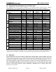
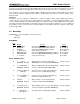
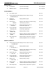
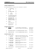
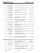
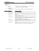
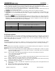
3.2 Adjustable Factory Setpoints for the TruSine 4500
The following chart lists the Factory Setpoints for all System functions which may be adjusted,
Enabled/Disabled, or turned ON/OFF using the optional TSR-2 Remote Control. (Software
A88769-A)
Inverter/Charger Model TSC24-4500 TSC24-4500D
Non-Password Protected
Function
Adj.
Range
Factory
Setpoint
Adjustment
Range
Factory
Setpoint
Inverter Same Same
Enabled/Disabled
Enabled
Load Demand Same Same
Enabled/Disabled
Enabled
Enter Load Demand Same Same 0 – 70 20 Watts
Exit Load Demand Same Same 0 – 255 40 Watts
Charger Same Same
Enabled/Disabled
Enabled
Equalize Cycle Same Same
Enabled/Disabled
Disabled
Basic Control
APM Limit Amps Same 30 Amps 0 – 60 30 Amps
Password Protected
Function
Inverter Output Voltage 110 - 125 120 VAC 110 – 125 120 VAC /phase
Low Battery Warning Voltage Same Same 20.0 - 25.0 22.0 VDC
Low Bat. Shutdown Voltage Same Same 20.0 - 22.0 21.0 VDC
Inverter
High Bat. Shutdown Voltage Same Same 25.0 - 34.0 34.0 VDC
Bulk Charge Voltage Same Same 26.0 - 32.0 28.4 VDC
Bulk Charge Amps Same Same 0 – 100 100 Amps
Absorption Charge Voltage Same Same 28.0 - 34.0 30.0 VDC
Absorption Charge Amps Same Same 10 – 50 50 Amps
Absorption Maximum Time Same Same 10 – 255 10 Minutes
Float Charge Voltage Same Same 26.0 - 30.0 26.4 VDC
Equalize Voltage Same Same 26.0 - 34.0 31.0 VDC
Equalize Maximum Time Same Same 5 – 30 15 Minutes
Battery Temp Compensation Same Same On - OFF OFF
Battery Temp Coefficient Same Same 0 – 25.5 4.0 mV/ºC/Cell
Battery Charger
Battery Temp Shut Down Same Same 0 – 255 50ºC
Gen Start Mode Same Same
ON/OFF
ON
Gen Start Batt Voltage Same Same 20.0 - 25.0 22.0 VDC
Gen
Gen Stop Charging Amps same Same 0 – 50 10 Amps
AC Line Stabilization Time Same Same 10 – 120 10 seconds
Trans
Switch
Solar Mode Same Same
ON/OFF
OFF
(address) Look for inverters? Yes - No No
Inverter Address (*see Note) Same Same 1 – 10 1
I D
Remote Address Same Same 1 – 10 1
*Note - Inverter Address, Step 92, applies only to systems having multiple inverters and multiple TSR-2
Remotes. Do not change Inverter Address from 1 in a single inverter system. The TSR-2 will immediately stop
responding if Inverter Address is changed. Use Demo Mode to change Step 92 ‘Inverter Address’ back to 1.
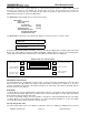
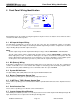
3.3 Operation
The TSR-2 Remote Control Panel contains: a Menu button; an Escape button; a two-line display; four control
buttons located at the corners of the two-line display; and an Alarm indicator light. The two-line display will
contain information that will instruct the operator to take action based on display characters at each “corner” of
the display. For example, if the display has an ‘up arrow’ in the left position of the upper display line, press the
upper left control button to step up in the menu sequence. Likewise, a ‘down arrow’ would instruct you to press
the corresponding control button to move down in the menu sequence. For data values, press the control
button corresponding a displayed +(plus sign) or – (minus sign) to increase or decrease the data value. System
functions are turned ON or OFF by selecting ‘ENABLED’ or ‘DISABLED’ from the display. Capital letters
indicate the selected status.