
Instruction manual

Installation Tank Gauge Transmitter
4 Installation and Operations Manual
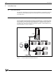
2.2 Mounting the Equipment
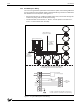
The ATT is bolted to the Model 2500 Automatic Tank Gauge head as illustrated in
Figure 2-2. It may also be mounted to Endress+Hauser, Sakura, Tokyo-Keiso, Shand &
Jurs, and Gauging Systems, Inc. float and tape gauges with the Endress+Hauser adapter
shown in the following table.
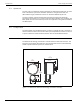
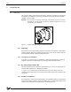
Mounting the ATT to the Level Gauge is accomplished in the following manner:
1. Remove the back cover of the Level Gauge.
2. Remove the access cap from the back cover of the Level Gauge.
3. Mount the ATT in place of the access cap, making certain that the word "TOP" cast
into the housing lines up with the top of the Level Gauge back cover.
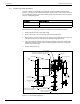
4. Install the Level Gauge back cover with the transmitter in the Level Gauge. Make
certain that the slot in the ATT drive coupling engages with the pin on the tape
sheave of the Level Gauge.
5. Proceed with field wiring.
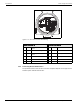
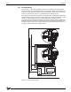
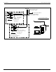
Figure 2-2: ATT Mounting Diagram
Part Number Gauge Adapter Kit
13-05956-102 L&J (Shand & Jurs) 92513, 92514, 92020, 92030
13-05956-202 Whessoe 2006, 2026, 2036 and L&J (Shand & Jurs) 92006
Sprocket Sheave
Pin drive
Back
cover
2500
Automatic
Tank Gauge
Transmitter
External enclosure ground
connection by installer
Drive coupling
5/16 split lock washers (4 places)
5/16-18 X 1 mounting bolts (4 places)
Integral junction
box
Junction
box cover
External Ground Lug
Back Cover
Gauge cover mounting
bolts (15 places)