
Specifications

52
Reference Manual
00809-0100-2460, Rev AA
Section 4: Configuration
November 2014
Configuration
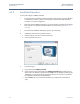
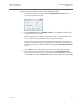
g. Enter the Temperature Device Address. For 2410 tank position 1 the same address is
used for the 2410 Tank Hub and the Temperature Device. The 2410 address is
automatically copied to the Temperature Device Address field.
For 2410 tank positions 2 to 10 you will have to enter the same addresses as configured
in the Tank Database of the 2410 Tank Hub. Each tank position must have a unique
Temperature Device Address.
Note! In the Tank Database of the 2410 Tank Hub, this address is referred to as the
ATD Modbus address.
See “Tank Databases of the 2460 System Hub and the 2410 Tank Hub” on page 55 for
more information on how the Tank Databases of the 2460 and 2410 relate to each
other.
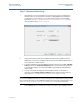
h. Type the number of elements in the Number of Temperature Elements column in
case temperature elements are installed in the tank. The position of the temperature
elements need to be configured in order to provide calculation of average product
temperature. This is normally done as part of the standard installation procedure for
the Rosemount 2410 Tank Hub and the associated temperature transmitters as
described in the Raptor System Configuration Manual (Document no. 300510).
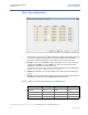
i. Select the Auxiliary Inputs that are used for the device such as Free Water Level (FWL),
Vapor Pressure (VP), and Liquid Pressure (LP). See Table 4-3 on page 53 for a complete
list of Auxiliary Inputs.
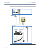
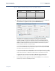
Level Device Address
The Level Device Address field in the Tank Database of the 2460 System Hub is used for level
gauges such as the Rosemount 5900S. This address also needs to be stored in the Tank Database
of the 2410 Tank Hub. Normally, address configuration is done as part of the installation
procedure of the Rosemount 2410 as described in the Rosemount Raptor System Configuration
Manual (Document No. 300510).
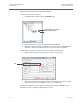
Temperature Device Address
The Temperature Device Address in the Tank Database of the 2460 System Hub is used for all
devices on a tank except level gauges. The Temperature Device address also needs to be stored in
the Tank Database of the 2410 Tank Hub. In the 2410 this address is referred to as the
ATD Modbus address.
Configuration of the 2410 Tank Database is normally done as part of the installation procedure
of the Rosemount 2410 as described in the Rosemount Raptor System Configuration Manual
(Document No. 300510).
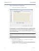
For the first tank position in the 2410 Tank Database, the 2410 Modbus address is automatically
set as the ATD Modbus address as illustrated in Figure 4-3 on page 57.
It is recommended that address range 1 to 99 is used for level gauges and 101 to 199 for ATD
devices.
See “Tank Databases of the 2460 System Hub and the 2410 Tank Hub” on page 55 for more
information on how to configure the databases of the 2460 System Hub and the 2410 Tank Hub.
See also section “Installing a Rosemount 2410 Tank Hub” in the Raptor System Configuration
Manual (Document No. 300510).