Varedan Technologies LA Series Stand-Alone Linear Amplifiers Product User Guide Revision A10
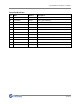
LA Stand-Alone Product User Guide Record of Revisions Rev Date Valid For Description A1 07/20/2011 All units Initial release A2 10/15/2011 All units Revise part numbering A3 11/11/11 All units Add connection drawing A4 6/1/2012 All units Correct mating CPC part numbers A5 6/18/2012 All units Add J8 Male pinout A6 7/27/2012 4016-RC Add optical isolation for new front panel A7 10/11/12 All units Add 800W version A8 08/11/14 All units Fix limit - opto input drawing A9 10/2
LA Stand-Alone Product User Guide Revision A7 Technical changes to improve performance may be made at any time without notice! All rights reserved. No part of this work may be reproduced in any form without written permission from Varedan Technologies.
LA Stand-Alone Product User Guide Revision A7 Contents 1 Introduction .......................................................................................................................................... 6 1.1 Model Numbering ............................................................................................................................. 7 1.2 Specifications 200W, 400W, 500W ................................................................................................. 7 1.
LA Stand-Alone Product User Guide Revision A7 4 Serial Parameter Settings .................................................................................................................. 27 4.1 P – Parameter Command .............................................................................................................. 27 4.2 Software Parameter Setting Table Summary................................................................................. 28 5 Troubleshooting .................................
LA Stand-Alone Product User Guide Revision A7 1 Introduction The LA Series Stand-Alone linear amplifier system is an AC line powered unit based on the LA series current-mode linear amplifiers.
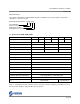
LA Stand-Alone Product User Guide Revision A7 Model Numbering The LA Series Stand-Alone Linear Amplifier System is available in various power options and in either single-phase or 3-phase models. Model Number Breakdown: LA-415-SA-T Linear Amplifier Power Level (see table) Stand Alone Package S=Single Phase, T= 3 phase 1.
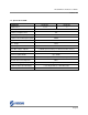
LA Stand-Alone Product User Guide Revision A7 1.2 Specifications 800W Parameter Output Phases LA-830-SA-S LA-830-SA-T 1 or 2 3 Peak Output Current 30A Continuous Output Current 15A Peak Output Power (25°C) 1500W Continuous Power Dissipation (25°C) 800W Weight 26.0lbs Size - Height 7.93 in. Size - Length x Width 17.70 in. x 8.75 in. Motor Bus Voltage – Bipolar +/-56VDC (Contact factory for other transformer choices) Max.
LA Stand-Alone Product User Guide Revision A7 1.3 Safety Information Read this information before operating this system. 1.3.1 Grounding The AC power connection to the box must have a connection to ground. CAUTION The LA StandAlone must be plugged into a properly grounded AC outlet. Failure to provide this ground could result in a fatal electric shock. Verify ground continuity to all metal pieces on the system. Metal components bolted only to granite may not be grounded.
LA Stand-Alone Product User Guide Revision A7 2 System Installation 2.1 Mechanical Dimensions 2.1.
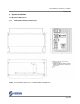
LA Stand-Alone Product User Guide Revision A7 2.1.2 800W Case Dimensions A A 0.21 17.28 4.03 7.93 A A 1.94 8.75 17.70 1.22 17.28 A Notes: A: 0.2in x 0.313in Slot for UNC 10-32 Screws (8 places) 1) All dimensions in inches A 6.22 A A 0.
LA Stand-Alone Product User Guide Revision A7 2.2 Selecting a mounting area The unit should be mounted in a solid, clean, dry location with adequate ventilation. Avoid mounting areas that: Obstruct the intake or exhaust of the internal forced air cooling. Allow dust, debris to enter and contaminate the cooling capability of the drive. Have humidity above 80% or are susceptible to moisture or coolant. Are prone to corrosive or flammable materials.
LA Stand-Alone Product User Guide Revision A7 2.3 Front Panel AC Power Switch ON / OFF AC Input Module AC Input Selector Panel 115 / 230VAC Fan Exhaust / Exit 14 Pin CPC Motor Connector USB Connector Reset Switch LED Display Signal Connector RS232 Interface Aux.
LA Stand-Alone Product User Guide Revision A7 2.3.1 AC Input The LA Stand-Alone amplifier can accept AC input voltages of 100 – 120 and 208 - 240VAC at 47 – 63Hz. Note that the Stand-Alone amplifier utilizes an unregulated linear power supply. Therefore a higher AC input (for a given range) will provide a higher voltage to the spindle and allow the spindle to reach higher velocities. The AC Inlet should be configured per the table below.
LA Stand-Alone Product User Guide Revision A7 2.4 Interface Connections 2.4.1 Pin 3 Motor Connector (J1) CPC-14 Pin 1 Pin 7 Pin 4 Pin 11 Pin 8 Pin 12 Pin 14 2.4.2 2.4.3 2.4.4 2.4.5 2.4.
LA Stand-Alone Product User Guide Revision A7 2.4.7 Signal Connector Electrical Interface The following drawings illustrate the electrical interface for the J8 & J9 signal connectors. Note that there are 2 configurations available from the factory, one with optical isolation and one without. Please be sure to use the correct drawing. Also note that J8 can be either DB15M (male) or DB15F (female). 2.4.7.
LA Stand-Alone Product User Guide Revision A7 2.4.7.2 J8 & J9 Electrical Interface, Non-isolated The following drawing shows the non-isolated interface for J8 and J9. Note: Pin outs are shown for DB15M connector option. Refer to 2.4.8 or 2.4.
LA Stand-Alone Product User Guide Revision A7 2.4.8 Signal Connector (J8) DB-15 Female Note: Two different genders of J8 are used. Be sure to use the correct pin out (Male or Female). Pin 8 Pin 15 Pin 1 Pin 9 Pin # Description 1 Common - Signal Ground 2 Limit + Input - Active high input, Internally pulled high (3.3V), set low to enable travel. Not used in Sine Mode. For optically isolated version see section 2.4.7.
LA Stand-Alone Product User Guide Revision A7 2.4.9 Signal Connector (J8) DB-15 Male Note: Two different genders of J8 are used. Be sure to use the correct pin out (Male or Female). Pin 1 Pin 8 Pin 9 Pin 15 Pin # Description 1 Command A+ Input - +/- 10vdc command input. Used in both Single Ended and Differential modes 2 Command A- Input - +/- 10vdc command input. Only used in Differential mode Note: Command A inputs are not used in single-phase mode 3 Command B+ Input - +/- 10vdc command input.
LA Stand-Alone Product User Guide Revision A7 2.4.10 RS232 Connector (J3) DB-9F Pin 5 Pin 9 Pin 1 Pin 6 Pin # Description 1 No Connection 2 RS232 Receive - Data into amplifier 3 RS232 Transmit - Data from amplifier 4 No Connection 5 Ground 6 No Connection 7 No Connection 8 No Connection 9 No Connection Note: Receive and Transmit pins are disabled if J2 (USB) is used for communication.
LA Stand-Alone Product User Guide Revision A7 2.4.11 Auxiliary I/O Connector (J9) DB-9M Pin 1 Pin 6 Pin 5 Pin 9 Pin # Description 1 Motor Temperature Switch Input - Ground to enable amplifier (switch closed). Pulled up to +5vdc. 2 Common - Use as return for Motor Temperature Switch. 3 Common - Ground 4 Hall C Input. For optically isolated version see section 2.4.7.1 5 Hall A Input. For optically isolated version see section 2.4.7.1 6 Hall B Input.
LA Stand-Alone Product User Guide Revision A7 2.4.12 7-Segment Display The 7 segment LED display on the front panel shows the status of the controller in real-time. The following table lists the front panel LED display codes and their meaning. If multiple errors are present, the display will cycle through all the error codes, displaying each for ½ second.
LA Stand-Alone Product User Guide Revision A7 Heatsink Over Temp – Set when the heat sink temperature is above 70 C. Remove power and allow the unit to cool before attempting to run again. Overcurrent – Set when amplifier detects an overcurrent condition. (“L”ow speed circuit breaker). Bus Under Voltage – Set when the internal motor bus voltage is less than +/-10 Vdc. Bias error – Set when the internal bias voltage input is outside the allowable range.
LA Stand-Alone Product User Guide Revision A7 3 Establishing Communications The LA StandAlone amplifier communicates via a RS232 port or USB port at 19200 baud. A serial communication program such as HyperTerminal can be used for communications. The standard settings are 8 data bits, 1 stop bit, no parity and no hardware or software handshaking. Settings Emulation = ANSIW.
LA Stand-Alone Product User Guide Revision A7 3.3 Serial Commands The following commands are supported over the serial port communications interface. 3.3.1 A – Alarm Reset This command allows viewing or resetting the alarm status. “A” with no parameter is used to read the alarm status. “A 1” is used to reset the alarm status. Note: When an alarm is detected by the system, the drive is immediately disabled. 3.3.2 B – AutoBalance This command is used to invoke the autobalance algorithm.
LA Stand-Alone Product User Guide Revision A7 3.3.9 M – Mode This command is used to view or set the commutation mode of the drive. M0 sets trapezoidal commutation, M1 sets Sinusoidal 2 phase input commutation. The “M command can only be used to view the commutation setting if jumpers are installed. 3.3.10 R – Reset This command causes the drive to perform a power on reset. 3.3.11 S – Save Parameters This command saves the user selectable parameters to NVM. 3.3.
LA Stand-Alone Product User Guide Revision A7 4 Serial Parameter Settings The user parameter settings are configured either by jumpers or via the serial interface. When jumpers are used, the serial interface can only be used to read the jumper settings. If no jumpers are installed, the software settings are used. If the configuration when using jumpers results in no jumpers being installed (Sine Mode with all minimum values), place a jumper on JP1-G.
LA Stand-Alone Product User Guide Revision A7 4.2 Software Parameter Setting Table Summary P0 – Transconductance value P0 Value LA-210 LA-415 LA-525 0 0.25 0.8 1.0 1 0.5 1.0 1.5 2 0.75 1.2 2.0 3 1.0 1.5 2.5 4 0.25 0.8 1.0 5 0.5 1.0 1.5 6 0.75 1.2 2.0 7 1.0 1.5 2.
LA Stand-Alone Product User Guide Revision A7 Figure 9.
LA Stand-Alone Product User Guide Revision A7 Figure 10.
LA Stand-Alone Product User Guide Revision A7 5 Troubleshooting 5.1 Autobalance The amplifier has a built-in algorithm for balancing the linear amplifier power stage. Normally it is not necessary to perform this procedure as the amplifier stage is balanced at the factory. Due to the inherent offsets of the analog circuitry in the power stage, offsets may occur in the system over time that cause unwanted torque ripple.
LA Stand-Alone Product User Guide Revision A7 6 Appendix A – Serial Interface Details This section describes the details of the serial communication messages. The only white space character used in this protocol is the Space (ASCII 0x20). All lines are terminated with a Carriage Return and Line Feed (cr/lf) followed by a “>” prompt (ASCII 0x3E). The prompt is sent following any message by the amplifier.
LA Stand-Alone Product User Guide Revision A7 6.2 Alarm Messages Sent in response to “A” command or upon detection of alarm condition. 16 possible responses, 14 characters in length. "Alarm "Alarm "Alarm "Alarm "Alarm "Alarm "Alarm "Alarm "Alarm "Alarm "Alarm "Alarm "Alarm "Alarm "Alarm "Alarm “>” = = = = = = = = = = = = = = = = DSP " NVM " HALLS " AMP OT" MOT OT" ABS OC" RMS OC" BUS OV" BUS UV" 5V REF" 15VREF" 2.5REF" 5V EXT" AUTOBL" SOA " FATAL " 6.
LA Stand-Alone Product User Guide Revision A7 6.5 Factory Default Message In response to the “F” command: "Loading Default Parameters" “>” 6.
LA Stand-Alone Product User Guide Revision A7 6.7 List Messages In response to the “L” command: “Bus+= 0 V” “Bus-=-0 V” “Vpha= 0 V” “Vphb= 0 V” “Vphc= 0 V” “Ipha= 0.0 A” “Iphb= 0.0 A” “Iphc= 0.0 A” “+15 = 15.2 V” “-15 =-15.2 V” “+5 = 4.9 V” “+5Ex= 4.9 V” “+2.5= 2.50 V” “-2.5=-2.
LA Stand-Alone Product User Guide Revision A7 6.10 Fault History Messages In response to the “Y” command: cr/lf “Alarm History (Last to First)” cr/lf “Alarm = BUS UV” cr/lf “Alarm = 15VREF” cr/lf “Alarm = 15VREF” cr/lf “Alarm = BUS UV” cr/lf “Alarm = 15VREF” cr/lf “Alarm = ABS OC” cr/lf “Alarm = BUS UV” cr/lf “Alarm = BUS UV” cr/lf “>” Note that this is just an example fault history. Actual results may vary, but all messages follow the format for the Alarm messages described earlier.
LA Stand-Alone Product User Guide Revision A7 6.12 SOA Fault History Messages In response to the “YS” command: cr/lf “Saved SOA History” cr/lf “Cnts= 0” “MaxP= 0 W” “ActP= 0 W” “Bus+= 0.0 V” “Bus-=-0.0 V” “Vpha= 0.0 V” “Vphb= 0.0 V” “Vphc= 0.0 V” “Ipha= 0.0 A” “Iphb= 0.0 A” “Iphc= 0.0 A” “Temp= 0 C” cr/lf “>” Note that this is an example message. Actual results will be displayed in the event of an actual SOA trip.
LA Stand-Alone Product User Guide Revision A7 7 Appendix B – Firmware Updates It may become necessary to update the firmware in the controller if a new release of code becomes available, or if additional features are added. Updates are easily done in the field using a personal computer with a USB or RS-232 serial interface port and a small application program that sends the updated code to the controller from the host PC.
LA Stand-Alone Product User Guide Revision A7 8 Sales and Service Varedan Technologies 3870 Del Amo Blvd Suite 503 Torrance, CA 90503 1-310-542-2320 www.varedan.com sales@varedan.