FOOD MIXER SPARE PART AND OPERATION MANUAL January 2008 Form 103 Model W20 A, J, F 1993 to Present
Caution -READ BEFORE OPERATING- Caution Varimixer recommends that mixer operators be at least 18 years of age and be thoroughly trained on the use of the mixer. Varimixer recommends that the following precautions be adopted to help make the mixer operation safer and more efficient. ........- All operators should be at least 18 years of age. - All operators should be thoroughly trained before being allowed to operate the mixer. - NEVER reach into the bowl when the mixer is running.
LIMITED WARRANTY Varimixer warrants its commercial mixers to the original purchaser against defects in material or manufacture for a period of one year from the date of original purchase, subject to the following exclusions and limitations. The warranties provided by Varimixer do not apply in the following instances: EXCLUSIONS 1. In the event that the equipment is improperly installed.
TABLE OF CONTENTS Installation Instructions...................................................................................................2 Cleaning Instructions.....................................................................................................2 Operating Instructions....................................................................................................3 Specifications......................................................................................................
INSTALLATION - CLEANING - MAINTENANCE INSTALLATION: The mixer can be placed directly on the floor. Foundation bolts in the floor are necessary only under special conditions, e.g. in ships. If the 20-quart mixer is placed on a bench stand, it must be fastened with the bolts that fasten the unit to the shipping pallet. Ensure that the voltage, phase and hertz printed on the identification plate of the mixer are the same as that at the place of installation.
Varimixer Operating Instructions W20 Place the bowl in the bowl arms. Be sure that the bowl is placed correctly and the bowl clamps are used. Place the mixing tool in the bayonet shaft. The pin of the tool must be turned into the bayonet hole. Set the time required by turning the timer to Start the mixer by pressing the green start the right. The mixer will stop automatically button. The mixer will only start with the when the time runs out. timer on and the bowl screen closed.
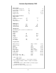
Varimixer Specifications W20 Dimesion Data Level Capacity of large bowl Level Capacity of small bowl Width Overall Depth Overall Height Overall Electrical Data for Motor** 60HZ / 1 Phase Voltage* Feed Wires incl. Ground Motor Power Amperes,full load Mixing Speed Agitator Speed Agitator Speed Attachment Hub Qt. Qt. In. In. In 21 13 17 7/8 26 1/2 34 7/8 V No. HP A 115 3 1 12 Min. Max. R.P.M.
SERVICE INSTRUCTIONS 6 10 22 1 7 9 40 41 16 8 2 55 3 21 43 4 5 44 42 18 17 5 20 19
SERVICE INSTRUCTIONS (1) Remove the top cover of the mixer (1) and the plastic cover (43) by removing the 2 screws (3) The attachment engagement hub is taken out by removing the plastic cover (4) and the 4 bolts (5). (6) The control box is taken off by removing the 2 screws (55). (7) The special V-belt is replaced in the following way: a) Remove the top cover of the mixer (1) and the plastic cover (43).
The planetary head is removed in the following way: a) The top cover of the mixer (1), the attachment engagement hub (3), the special V-belt (7), and the control box (6) are removed. b) The plastic ring (26) can be removed by knocking it gently on the front edge, then pressing a screwdriver between the plastic ring and the metal plate at the top of the plastic ring. c) Remove the rubber ring (27).
9 B C See Drawing A 16 8 39 32 35 15 34 7 11 Mounting of the planetary head should be done in reverse order. 12 When the lower fork (15) and the spring (34) are mounted, the speed selector lever (8) is turned counter clockwise, so that it points horizontally backward, at the same time as the lower fork is pressed down gently. When the speed selector lever (8) is turned clockwise, it will catch the toothed rack (35) and pull down the lower fork. Screw on the nuts (11) and (12).
50 52 51 50 53 54 D 47 56 46 48 45 49 45 17 18 20 19 (45) The bowl arms are to be replaced in the following way: a) Disconnect the mixer on the main switch or disconnect the connecting cable. b) Lower the bowl arms. c) Place the mixer on its back and remove the legs of the mixer (17) by removing the screws (18). d) The bottom plate (19) is removed by removing the nuts (20). e) Remove the cotter pin (51), securing the lifting bolt (46) and the lifting nut (47).
10
Body 1 2 3 4 5 6 7 8 9 10 14 13 15 11 12 16 17 18 19 20 21 11
Body Figure Number 1. 2. 3. 4. 5. 6. 7. 8. 9. 10. 11. 12. 13. 14. 15. 16. 17. 18. 19. 20. 21. Description Screw Top Lid (Painted) Rear Access Plate Bushing (Lift Handle) Upper Column Plug Button Bushings Column Seal Plug Button Lower Column Bolt M8X20 Leg Left Leg Right Plug Button Rubber Foot NSF Cover Plate Suspension Hook Column Base Plate Retaining Spring f/Plate Lock Nut M6 Mixer Mount Bolt 12 Part Number STA 5233 20D-21 20N-291 STA 2515 20N-22.17 STA 6561 STA 2514 (each) 20N-207 STA 6511 20N-22.
Bowl Arms 1 7 6 2 3 10 4 5 8 11 9 12 20 13 15 14 21 16 22 19 17 56RN20-15 20N-62Z 18 20N-65.1Z 20N-65.
Bowl Arms Figure Number Description Part Number 1. 2. 3. 4. 5. 6. 7. 8. 9. 10. 11. 12. 13. 14. 15. 16. 17. 18. 19. 20. 22 21. 22. Ball (Black) Bowl Lift Lever Washer Disc Retaining Disc Crank Arm Cotter Pin Key Snap Ring Lift Nut Jam Nut Lift Bolt Bowl Arm Shaft Snap Ring 25U Bowl Arm Snap Ring 25U Bowl Lift Lever Assembly Lift Bolt Assembly Bowl Arm Shaft Bowl Lift Microswitch Assembly Right Bowl Clamp Left Bowl Clamp STA 3306 20N-62Z STA 6066 20N-47.10 20N-47.
Pulley System 8 9 16 32 13 33 2 14 6 24 27 29 12 18 25 7 27 32 1 12 31 5 3 10 34 23 20 4 30 21 27 40 28 35 26 36 37 38 15
Pulley System Figure Number Description Part Number 1. 2. 3. 4. 5. 6. 7. 8. 9. 10. 11 12. 13. 14. 15. 16. 17. 18. 19. 20. 21. 22. 23. 24. 25. 26. 27. 28. 29. 30. 31. 32. 33. 34. 35. 36. 37. 38. 39. 40.
Pulley System Model W20P Single Speed Pizza Mixer 4 5 6 7 1 3 2 8
Pulley System Model W20P Single Speed Pizza Mixer Figure Number Description Part Number 1. 2. 3. 4. 5. 6. 7. 8. Belt Motor Pulley Planetary Pulley Bolt 3/8-16X3/4 Washer Bolt M6X16 Washer Motor 20P-91 6J19 6J60 STA 5442 STA 6009 STA 5432 STA 6008 20D-85.
Planetary Head 1 2 3 4 5 6 7 8 12 13 9 14 15 10 16 20 17 11 21 18 22 19 23 24 25 26 27 28 29 30 31 32 20N-2.1Z 20N-3 20N-2 20N-2.
Planetary Head Figure Number Description Part Number 1. 2. 3. 4. 5. 6. 7. 8. 9. 10. 11. 12. 13. 14. 15. 16. 17. 18. 19. 20. 21. 22. 23. 24. 25. 26. 27. 28. 29. 30. 31. 32. 33. 34. 35.
Attachment Drive 1 2 3 4 5 6 7 8 9 11 10 12 13 14 15 1 1/2” I.D. 2” I.D. 20N-10.6M 20N-10.5M #17 Hub 20N-10.
Attachment Drive Figure Number 1. 2. 3. 4. 5. 6. 7. 8. 8A. 9. 10. 10A. 11. 11A. 12. 13. 14. 15. 15A. Description Part Number Snap Ring Wormwheel Snap Ring Bearing Distance Piece Bearing Key Shaft F/ #17 Hub Shaft F/ #12 Hub O-ring Hub F/ #17 (2” I.D.) Hub F/ #12 (1 1/2” I.D.
Electrical Components 1993-mid 1997 1 3 3A 2 6 9 8 7 4 10 11 5 12 14 15 17 16 21
Electrical Components 1993-mid 1997 Figure Number Description Part Number 1. 2. 3. 3A 4. 5. 6. 7. 8. 9. 10. 11. 12. 13. 14. 15. 16. 17.
Electrical Components 1998-Present 6A 6 1 7 2 3 5 18 4 19 8 17 16 9 15 14 10 13 11 12 23
Electrical Components 1998-Present Figure Number Description Part Number 1. 2. 3. 4. 5. 6. 6A 7. 8. 9. 10. 11. 12. 13. 14. 15. 16. 17. 18. 19. Start Switch Assembly Stop Switch Assembly Timer Assembly 115V Timer Knob Timer Scale Front Panel Assembly No Hub Front Panel Assembly Hub Front Foil w/ Hub Motor Cable Grommet Tension Relief ScScrew Screw Contactor Bracket Auxiliary Switch Contactor 110V 16 A Thermal Overload 11-16 Screw Motor Mount Plate Bolt Washer 31-174.2 31-174.3 20-188.
Bowl Screen 2 3 4 10 8 11 6 5 9 7 12 13 1 14 15 16 18 17 25
Bowl Screen Figure Number Description Part Number 1. 2. 3. 4. 5. 6. 7. 8. 9. 10. 11. 12. 13. 14. 15. 16. 17. 18. Bowl Screen Kit Bushing Cam Set Screw Screw Microswitch Set Screw Cam Spacer Bolt Nut Bushing Bracket Assembly Nut Bolt Rear Screen Front Screen Chute 225/20N 56SN20-21.1 56SN20-21 STA 5664 STA 5251 56SN20-30 STA 5664 56SN20-22.1 56SN20-24 STA 5850 STA 5816 56SN20-21.
Tools and Attachments 19 1, 2 ,3 19 19 4, 5 6, 7 8 19 19 16 12, 13 24 26 25 19 27 22, 22A 21, 21A 20 27 23, 23A
Tools and Attachments Figure Number 1. 2. 3. 4. 5. 6. 7. 8. 12. 13. 16. 19. 20. 21. 21A 22. 22A 23. 23A 24. 25. 26. Description Part Number S/S Bowl 20Qt S/S Bowl 12Qt. S/S Bowl 25Qt. S/S Hook 20Qt. S/S Hook 12Qt. Flat Beater 20Qt. Flat Beater 12Qt. S/S Flat Beater 20 Qt. Wire Whip 20 Qt. Wire Whip 12 Qt. S/S Wing Whip 20 Qt. Pin Rack Bowl Scraper 20 Qt. Bowl Scraper 12 Qt. Arm W / Blade 20 Qt. Arm W / Blade 12 Qt. Nylon Blade 20 Qt. Nylon Blade 12 Qt.
29
30
5489 Campus Drive Shreveport LA 71129 (800) 222-1138 (318) 635-3131 Fax www.varimixer.