SPARE PART AND OPERATION MANUAL FOOD MIXER Model W20D
Caution -READ BEFORE OPERATING- Caution Varimixer recommends that mixer operators be at least 18 years of age and be thoroughly trained on the use of the mixer. Varimixer recommends that the following precautions be adopted to help make the mixer operation safer and more efficient. ........- All operators should be at least 18 years of age. - All operators should be thoroughly trained before being allowed to operate the mixer. - NEVER reach into the bowl when the mixer is running.
LIMITED WARRANTY Varimixer warrants its commercial mixers to the original purchaser against defects in material or manufacture for a period of one year from the date of original purchase, subject to the following exclusions and limitations. The warranties provided by Varimixer do not apply in the following instances: EXCLUSIONS 1. In the event that the equipment is improperly installed.
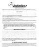
TABLE OF CONTENTS Installation Instructions...................................................................................................2 Cleaning Instructions.....................................................................................................2 Operating Instructions....................................................................................................3 Front Panel Controls...................................................................................................
Read this page entirely BEFORE beginning installation. VARIMIXER INSTALLATION INSTRUCTIONS The mixer must be mounted with the rubber feet, which neutralize both shaking and rusting. If the unit is to be installed on top of a table, the unit must be bolted down with the two bolts supplied from the shipping pallet. Before the mixer is connected to power, it should be checked that the voltage and frequency on the rating plate is correct in relation to the place of installation.
Operation of the Mixer. Power Up and Default: 1. Turn power on Mixer. (Plug in 115AC) - 1:00 Appears on the display. - The slow speed LED lights. (Left LED) 2. Press the bar arrow between the slow and fast LEDs. - 2:00 Appears on the display. - The fast speed LED lights. (Right LED) 3. Press the bar arrows between the slow and fast LEDs. Note: These are the factory default times for slow and fast speed. The computer will go to factory or stored times on every power up. Setting The Slow Speed Time: 1.
Operation of the Mixer. Change Time in Fixed mode: 1. Press and hold the bar arrow key for 5 sec. and release. 2. The fixed time for the slow speed will appear in the display. - The LED for slow speed lights. (Left LED) 3. Press the time up keys under the display to enter the desired time for slow speed. 4. Press the bar arrow key. 5. The fixed time for the fast speed will appear in the display. - The LED for fast speed lights.(Right LED) 6.
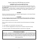
Body 1 2 3 4 5 6 7 8 9 10 14 13 15 11 12 16 5
Body Figure Number 1. 2. 3. 4. 5. 6. 7. 8. 9. 10. 11. 12. 13. 14. 15. 16. Description Screw Top Lid (Painted) Rear Access Plate Bushing (Lift Handle) Upper Column Plug Button Bushings Column Seal Plug Button Lower Column Bolt M8X20 Leg Left Leg Right Plug Button Rubber Foot NSF Cover Plate 6 Part Number STA 5233 20D-21 20N-291 STA 2515 20N-22.17 STA 6561 STA 2514 (each) 20N-207 STA 6511 20N-22.30 STA 5631 20N-25.1 20N-25.
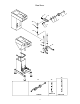
Bowl Arms 1 7 6 2 3 10 5 4 8 11 9 12 13 14 15 16 19 17 18 20N-62Z 7 20N-65.1Z 20N-65.
Bowl Arms Figure Number Description Part Number 1. 2. 3. 4. 5. 6. 7. 8. 9. 10. 11. 12. 13. 14. 15. 16. 17. 18. 19. Ball (Black) Bowl Lift Lever Washer Disc With Arrow Retaining Disc Crank Arm Cotter Pin Key Snap Ring Lift Nut Jam Nut Lift Bolt Bowl Arm Shaft Snap Ring 25U Bowl Arm Snap Ring 25U Bowl Lift Lever Assembly Lift Bolt Assembly Bowl Arm Shaft Assembly STA 3306 20N-62Z STA 6066 20N47.10 20N-47.11 20N-63M STA 6204 STA 2019 STA 3407 20N-65.1Z STA 5825 20N-83.1 20N-68.
Pulley System 4 5 6 7 1 3 2 8 9
Pulley System Figure Number Description Part Number 1. 2. 3. 4. 5. 6. 7. 8. Belt Motor Pulley Planetary Pulley Bolt 3/8-16X3/4 Washer Bolt M6X16 Washer Motor 20P-91 6J19 6J60 Local Purchase Item STA 6009 STA 5432 STA 6008 20D-85.
Planetary Head 1 2 3 4 5 6 7 8 12 13 9 14 15 10 16 20 17 11 21 18 22 19 23 24 25 26 27 28 29 30 31 32 20N-2.1Z 20N-3 20N-2 20N-2.
Planetary Head Figure Number Description Part Number 1. 2. 3. 4. 5. 6. 7. 8. 9. 10. 11. 12. 13. 14. 15. 16. 17. 18. 19. 20. 21. 22. 23. 24. 25. 26. 27. 28. 29. 30. 31. 32. 33. 34. 35.
Attachment Drive 1 2 3 4 5 6 7 8 9 11 10 12 13 14 15 1 1/2” I.D. 2” I.D. 20N-10.6M 20N-10.5M #17 Hub 20N-10.
Attachment Drive Figure Number 1. 2. 3. 4. 5. 6. 7. 8. 8A. 9. 10. 10A. 11. 11A. 12. 13. 14. 15. 15A. Description Part Number Snap Ring Wormwheel Snap Ring Bearing Distance Piece Bearing Key Shaft F/ #17 Hub Shaft F/ #12 Hub O-ring Hub F/ #17 (2” I.D.) Hub F/ #12 (1 1/2” I.D.
Computer Display Control 2 6 1 3 4 7 5 15
Computer Display Control Figure Number Description Part Number 1. Control Panel Assembly with start/stop buttons and computer display. Start Button Assembly Stop Button Assembly Screw Interface Board Assembly Front Plate Casting Ribbon Cable Cube Relay 20E-605M 2. 3. 4. 5. 6. 7. 8. 16 31-174.2 31-174.3 STA 5230 20E-606 20N-650.
Bowl Screen 2 3 4 10 8 11 6 5 9 7 12 13 1 14 15 16 18 17 17
Bowl Screen Figure Number Description Part Number 1. 2. 3. 4. 5. 6. 7. 8. 9. 10. 11. 12. 13. 14. 15. 16. 17. 18. Bowl Screen Kit Bushing Cam Set Screw Screw Microswitch Set Screw Cam Spacer Bolt Nut Bushing Bracket Assembly Nut Bolt Rear Screen Front Screen Chute 225/20N 56SN20-21.1 56SN20-23 STA 5664 STA 5251 56SN20-30 STA 5664 56SN20-22.1 56SN20-24 STA 5850 STA 5816 56SN20-21.
Tools and Attachments 19 1, 2 ,3 19 19 4, 5 6, 7 8 19 19 16 12, 13 24 26 25 19 27 22, 22A 21, 21A 20 19 23, 23A
Tools and Attachments Figure Number Description Part Number 1. 2. 3. 4. 5. 6. 7. 8. 12. 13. 16. 19. 20. 21. 21A 22. 22A 23. 23A 24. 25. 26. S/S Bowl 20Qt S/S Bowl 12Qt. S/S Bowl 25Qt. S/S Hook 20Qt. S/S Hook 12Qt. Flat Beater 20Qt. Flat Beater 12Qt. S/S Flat Beater 20 Qt. Wire Whip 20 Qt. Wire Whip 12 Qt. S/S Wing Whip 20 Qt. Pin Rack Bowl Scraper 20 Qt. Bowl Scraper 12 Qt. Arm W / Blade 20 Qt. Arm W / Blade 12 Qt. Nylon Blade 20 Qt. Nylon Blade 12 Qt.
Wiring Diagram Start .3 N.O. .4 Stop .1 N.C. .
Bowl Height Adjustment 10 9 1 7 2 3 8 4 6 5 A) Lower the bowl arms. B) Loosen the counter nut (2) and remove the cotter pin. (1) C) Remove the lifting bolt (6) and the lifting nut. (8) D) Adjust the bowl height by turning the lifting nut (8) either in or out, on the .....lifting bolt. E) Mount the lifting bolt with the lifting nut and the cotter pin, tighten the the .....counter nut. (2) D) Ensure all mixing tools fit and do not hit the bowl.
Planetary Head Removal 4 3 2 1 5 6 7 13 8 10 11 12 9 GREASE TYPES .....-On repair of the planetary head: Grease the toothed wheel and the toothed rim with Nye Gel .868VH, (PN WHITE GREASE), the needle bearings in the planetary head must not be ...........lubricated with this type of grease, they should be lubricated with Lubriplate #1200-2. .........Do not use any other type of grease than the ones stated here. ........
Planetary Head Removal 1. Remove the top lid (1), attachment hub (7), the drive belt (2) and the front ....control panel (4). 2 2. The plastic ring (13) can be removed with a screwdriver by pressing it ....between the plastic ring and the frame, and then prying it down. 2 . 3. Remove the rubber ring (10) and the stainless steel cover (12) by prying it ....off with a screwdriver. 2 4. If only the lower part of the planetary head is to be repaired, the planetary ....
5489 Campus Drive Shreveport LA 71129 (800) 222-1138 (318) 635-3131 Fax