SPARE PART AND OPERATION MANUAL FOOD MIXER Models W30(A), W40(A), W40P, W60(A) and W60P
Caution -READ BEFORE OPERATING- Caution Varimixer recommends that mixer operators be at least 18 years of age and be thoroughly trained on the use of the mixer. Varimixer recommends that the following precautions be adopted to help make the mixer operation safer and more efficient. ........- All operators should be at least 18 years of age. - All operators should be thoroughly trained before being allowed to operate the mixer. - NEVER reach into the bowl when the mixer is running.
LIMITED WARRANTY Varimixer warrants its commercial mixers to the original purchaser against defects in material or manufacture for a period of one year from the date of original purchase, subject to the following exclusions and limitations. The warranties provided by Varimixer do not apply in the following instances: EXCLUSIONS 1. In the event that the equipment is improperly installed.
TABLE OF CONTENTS Installation Instructions...................................................................................................2 Operating Instructions.....................................................................................................3 Cleaning-Maintenance....................................................................................................4 Belt Adjustments and Removal.......................................................................................
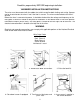
Read this page entirely BEFORE beginning installation. VARIMIXER INSTALLATION INSTRUCTIONS The mixer must be mounted with the rubber feet, which neutralize both shaking and rusting. Spacers can be inserted under the mixer’s feet if the floor is uneven. The mixer can be bolted to the floor if desired. Before the mixer is connected to power, it should be checked that the voltage and frequency on the rating plate is correct in relation to the place of installation.
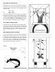
OPERATION OF THE MIXER: A) Open the bowl screen and place the bowl in the bowl arms. Note: The bowl arms must be in lowest position and the bowl must be pushed all the way into the bowl arms.(Fig.3). B) Place the mixing tool in the bayonet shaft. The pin on the tool must be turned into the bayonet hole (fig.2). C) The bowl is raised to working position by turn of the button for bowl lift (fig.1), ensure that the bowl is placed correctly. Close the bowl screen.
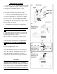
Correct use of tools: Maintenance and Lubrication: Whips should never be struck against hard objects, this will decrease the life of the tool. Recommended applications for tools: Whip Cream Egg Whites Mayonnaise and the like. Beater Cakes Waffles Muffins and the like. Hook Pizza Bread Donut Doughs and the like. Cleaning: The variable speed pulleys must be lubricated regularly, i.e. a lubrication interval of approx. 60 hours of operation.
Belt Adjustments and Removal To remove V-belts or tooth belt: 1. Remove the 4 screws (T) from the control panel. 2. Remove the front control (U) from mixer and let hang from cables. 3. Open lid. 4. Remove nut (J) and washers (H). 5. Remove fork assembly (X). 6. Roll belt (A) off of the the pulleys and remove. 7. Lossen jam nut (E) and tension bolt (F). 8. Loosen bolts (D). 9. Remove 3 V-belts or single tooth belt from planetary pulley (Y) and pedestal assembly (S).
6
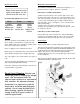
ADJUSTMENT OF BOWL HEIGHT: The distance (X) is measured from the bottom side of the bayonet hole to the surface on the bowl arms on which the bowl rests (fig.7a). The bowl arms must be lifted to normal working position. W30 = 6 3/8” W40 = 6 3/8” W60 = 6 15/16” Lower the bowl arms down on a wooden block so that the weight of the bowl arms are not loading the lifting system. Loosen the counter nut (1), (fig.7b). Take out the cotter pin (2). Take out the lifting rod (3).
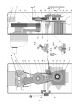
19 16 3 14 15 18 23 17 22 25 26 24 6 10 20 10 27 4 29 5 28 12 13 9 8 30 1.
MACHINE COLUMN DESCRIPTION PART NUMBER W30(A) W40(A) W40P See Figure See Figure See Figure See Figure See Figure 2. Mounting Screws STA 5270 STA 5270 STA 5270 STA 5270 STA 5270 3. Top Lid Threaded Bushing STA 6580 STA 6580 STA 6580 STA 6580 STA 6580 4. Knee Pad 30N-212 30N-212 30N-212 60N-212 60N-212 5. Intermediate Piece 6 MM 30N-214.6 30N-214.6 30N-214.6 60N-214.6 60N-214.6 6. Indicator Arrow 15-245 15-245 15-245 15-245 15-245 8.
9 3 15 13 8 11 16 16 18 17 12 21 15 19 22 23 2 18 15 25 16 26 24 27 28 29 5 30 3 2 7 1, 1A, 1B, 1C 4 11 5 6
BOWL ARMS PART NUMBER FIG. NO. DESCRIPTION W30 (A) W40 (A) W40P W60 (A) W60P 1. Bowl Arm Left (Pre 1993) 27-23 40-23 40-23 60-23 60-23 1A. Bowl Arm Right (Pre 1993) 27-24 40-24 40-24 60-24 60-24 1B. Bowl Arm Left 30N-23 40N-23 40N-23 60N-23 60N-23 1C. Bowl Arm Right 30N-24 40N-24 40N-24 60N-24 60N-24 2. Shock Absorber 40P-600M 40P-600M 40P-600M 60-600M 60-600M 3. Crank Arm 27-63 27-63 27-63 60-63 60-63 4. Bowl Arm Shaft 31-68 31-68 31-68 61-68 61-68 5.
17 18 1 19 20 2 21 3 18 4 22 17 5 23 6 26 7 24 25 27 8 9 10 28 29 6 30 29 31 5 32 34 33 35 11 34 36 12 14 39 37 38 13 40 15 16 13
PLANETARY HEAD PART NUMBER per MODEL NUMBER FIG. NO. DESCRIPTION W30 (A) W40 (A) W40P W60 (A) W60P 40-90.1 (A29) 40-90 (710LA) N/A STA 3425 STA 6043 40-129A 40-129 N/A 40-99 STA 3520 STA 5346 STA 6057 30-3 40-141 30-1 STA 5044 30-22.9P 30-2M 30-3M 30-2.1M 40-34 STA 3520 STA 3472 30-36 40-100 30-96 STA 2030 30-31 30-32 30-30 See Item 32 30-2 STA 6055 STA 5640 30-108R 30-101 STA 5641 40-34 30-97 STA 3522 STA 2038 30-33D 30-272 30-209 40-90.
48 22 23 50 10 31 34 1 30 45 37 2 41 20 3 37 28 46 38 5 40 29 29 6 19 4 39 50 21 37 14 44 25 25 11 24 32 33 42 9 47 51 35 8 49 43 7 52 36 12 54 17 13 18 16 15 13 12 11 26 27 55 53 15 56 57
TRANSMISSION PART NUMBER per MODEL NUMBER FIG. NO. DESCRIPTION 0 1. Washer 2. Upper Pulley for Pedestal 3. Pin 4. Bearing 5. Lower Pulley 6. Bushing 7. V-Belt Pulley 7A . Single Cog Belt Pulley 8. Shaft 9. Key 10. Grease Nipple 11. Snap Ring 12. Bearing 13. Snap Ring 14. Fork Ring 15. Distance Piece 16. Arm for Bearing 17. Bolt 18. Washer 19. Vari-Drive Belt 20. Bearing 21. Reducer 22. Grease Nipple 23. Washer 24. Lower Motor Pully 25. Pin for Motor Pulley 26. Lower Motor Pulley Assembly 27.
1 6 5 2 3 7 17 4
SPEED LEVER ASSEMBLY PART NUMBER per MODEL NUMBER FIG. NO. DESCRIPTION W30 (A) W40 (A) W40P W60 (A) W60P 30N-47M 30N-47.10 30N-47.20 STA 3306 STA 3414 STA 5247 40N-47M 30N-47.10 30N-47.20 STA 3306 STA 3414 STA 5247 40N-47M 30N-47.10 30N-47.20 STA 3306 STA 3414 STA 5247 60N-47M 30N-47.10 30N-47.20 STA 3306 STA 3414 STA 5247 60N-47M 30N-47.10 30N-47.20 STA 3306 STA 3414 STA 5247 0 1. 2. 3. 4. 5. 6.
DRIVE SYSTEM FOR MODEL W40PI AND W60PI SPECIAL SINGLE SPEED TRANSMISSION 5 1 6 2 7 3 8 9 4 10 12 17 13 14 16 15 13 12 11 19
SINGLE SPEED TRANSMISSION PART NUMBER FIG. NO. DESCRIPTION W40PI W60PI 33V315 STA 5018 60-61 N/A 3VX400 33V80 STA 3410 15-41 STA 2022 27-128 STA 3410 27-102 STA 3514 STA 6010 15-143 30-6 STA 5348 33V315 STA 5018 60-61 N/A 3VX425 33V80 STA 3410 60-41 STA 2022 60-128 STA 3410 27-102 STA 3514 STA 6010 15-143 30-6 STA 5348 0 1. 2. 3. 4. 5. 6. 7. 8. 9. 10. 11. 12. 13. 14. 15. 16. 17.
17 22 32 4 9 16 14 6 15 31 5 3 19 23 18 2 19 21 18 20,12 17 7 7A 26 26A 10 20 11,12 13,12 8 29 27 1 30 33 25 25A 24 IDENTIFYING A #17 HUB VERSUS A #12 HUB 2” I.D. #17 1.5” I.D.
ATTACHMENT DRIVE GEARBOX PART NUMBER FIG. NO. DESCRIPTION W30 (A) 0 1. Bearing Hub 15-5 2. Wormwheel 20-9 3. Gear Case 15-10 4. Gear Case Cover 15-11 5. Worm Gear 20-49 6. Gear Shaft 20-52 7. Attachment Drive Shaft # 17 15-50 7A. Attachment Drive Shaft # 12 30-50 8. Key STA 2032 9. Bearing 20-104 10. Seal 20-107 11. Gasket Use RTV Silicone 12. Gasket Use RTV Silicone 13. Gasket Use RTV Silicone 14. Key STA 2007 15. Key STA 2011 16. Snap Ring STA 3410 17. Screw STA 5018 18. Bearing 15-105 19.
17 3 8 1 5 6 4 9 12 10 11 7 2 14 12 15 16 17 18 19 20 21 23
ELECTRICAL PANEL 1985 - JUNE 1998 PART NUMBER FIG. NO. 0 1. 1a 2. 2. 3. 3A. 4. 5. 6. 7. 8. 9. 10. 11. 12. 13. 14. 15. 15A. 15B. 15C. 16. 17. 17A. 17B. 17C. 18. 19. 20. 21. 22. DESCRIPTION Electrical Control Assembly 208-240V 3 Phase Electrical Control Assembly 230V 1 Phase Timer Assembly 208-240V Timer Assembly 480V Start Button Green Stop Button Orange Pilot Light Front Panel N/A Timer Scale Screw Timer Knob Screw Cable Inlet Nut Thermal Overload 3 Ph. 220V Thermal Overload 3 Ph.
2 3 1 4 5 9 8 7 6 12 10 11 13 16 14 15 18 19 25 17
ELECTRICAL PANEL JULY 1998 - PRESENT PART NUMBER FIG. NO. 0 1. 2. 3. 4. 5. 6. 7. 8. 9. 10. 11. 12. 13. 14. 15. 15A. 15B. 15C. 16. 16A. 16B. 16C. 17. 18. 19. DESCRIPTION Front Panel Start Switch Assembly Stop Switch Assembly Timer Assembly 220V Timer Scale Screw Nut Cable Inlet Cable Inlet Cover Nut Timer Knob Grounding Clamp Screw Contactor 3 Ph. 220V Contactor 3 Ph. 480V Contactor 1 Ph. 230V Contactor 1 Ph. 115V Thermal Overload 3 Ph. 220V Thermal Overload 3 Ph. 480V Thermal Overload 1 Ph.
9 9 15 14 18 17 11 16 8 10 13 18 16 1 2 4 12 7 6 3 5 27
BOWL SCREEN 1993 - PRESENT PART NUMBER FIG. NO.
29
30
31
32
33
VEGETABLE SLICER / CHEESE GRATER FIG NO. ........ ..1. 1A. 2. 3. 4. 4A. 8. 8A. 8B. 8C. 10. 11. 12. 13. 14. 15. 16. 17. 18. 18A. 19. 20. 21. 24. 24A.
35
VEGETABLE SLICER / CHEESE GRATER ACCESSORIES FIG NO. ....... 1. .3. 8. 9. 10. 11. 12. 13. 14. 15. 16. 17. 18. 19. 20. 21. 23. 29. 30. 32. 33. 34. 35. 36. 37.
37
38
39
70 MM Meat Grinder FIG NO. DESCRIPTION PART NUMBER . ...... 1. 1A. 2. 3. 4. 5. 6. 7. 8. 9. 10. 11. 12. 13. 14. 15. 16. 17. 18. 19. 21. 22. 22A. 23. 23A. 24. 25.
41
86 MM Meat Grinder FIG NO. DESCRIPTION PART NUMBER ....... 1. 1A. 2. 4. 5. 5A 6. 7. 8. 9. 9A. 9B. 9C. 10. 11. 12. 13. 14. Housing #17 Housing #12 Key Bushing Worm with Pin #17 Worm with Pin #12 O-Ring Precutter Knife Disc 1/16” Disc 1/8” Disc 3/16” Disc 1/4” Tightening Ring Cap Meat Tray Stomper Tray (Optional) 6R001M 6R001 STA 2082 6R388 6R003M 6R003 6R340 308 306/KNIFE 306/2 306/3 306/5 306/8 6R345 6R002 6R250 6R351 330 IDENTIFYING A #17 HUB VERSUS A #12 HUB 2” I.D. 1.5” I.D.
43
BOWL SCRAPER 1985-2000 (SCREW TYPE) Fig. No.
45
KEYHOLE BOWL SCRAPER 2000- Fig. No.
8 5 11 12 , 13 6,7 3,4 1, 2 11 9 , 10 11 11 11 16 , 17 14 , 15 18 , 19 22 23 24 20 , 21 26 27 , 28 29 30 47
ATTACHMENTS AND OPTIONAL PRODUCTS PART NUMBER FIG. NO. DESCRIPTION W30 (A) W40 (A) W40P W60 (A) W60P 203/30A 203/15 213/30A 213/15 30-79 213/30D 213/15 30-79D 205/30A 205/15 STA 6261 207/30A 207/15 221/30A N/A 209/30A N/A 204/30A 204/15 215/30A 215/15 22R270 STA 6513 STA 5602 22R30-40 STA 5608 22R140.1-1W 22R140.
1985 - June 1998 1 Phase 49
1985 - June 1998 3 Phase 50
1998 - Present 1 Phase 51
1998 - Present 3 Phase 52
5489 Campus Dr. Shreveport LA 71129 (800) 222-1138 (318) 635-3131 Fax www.varimixer.