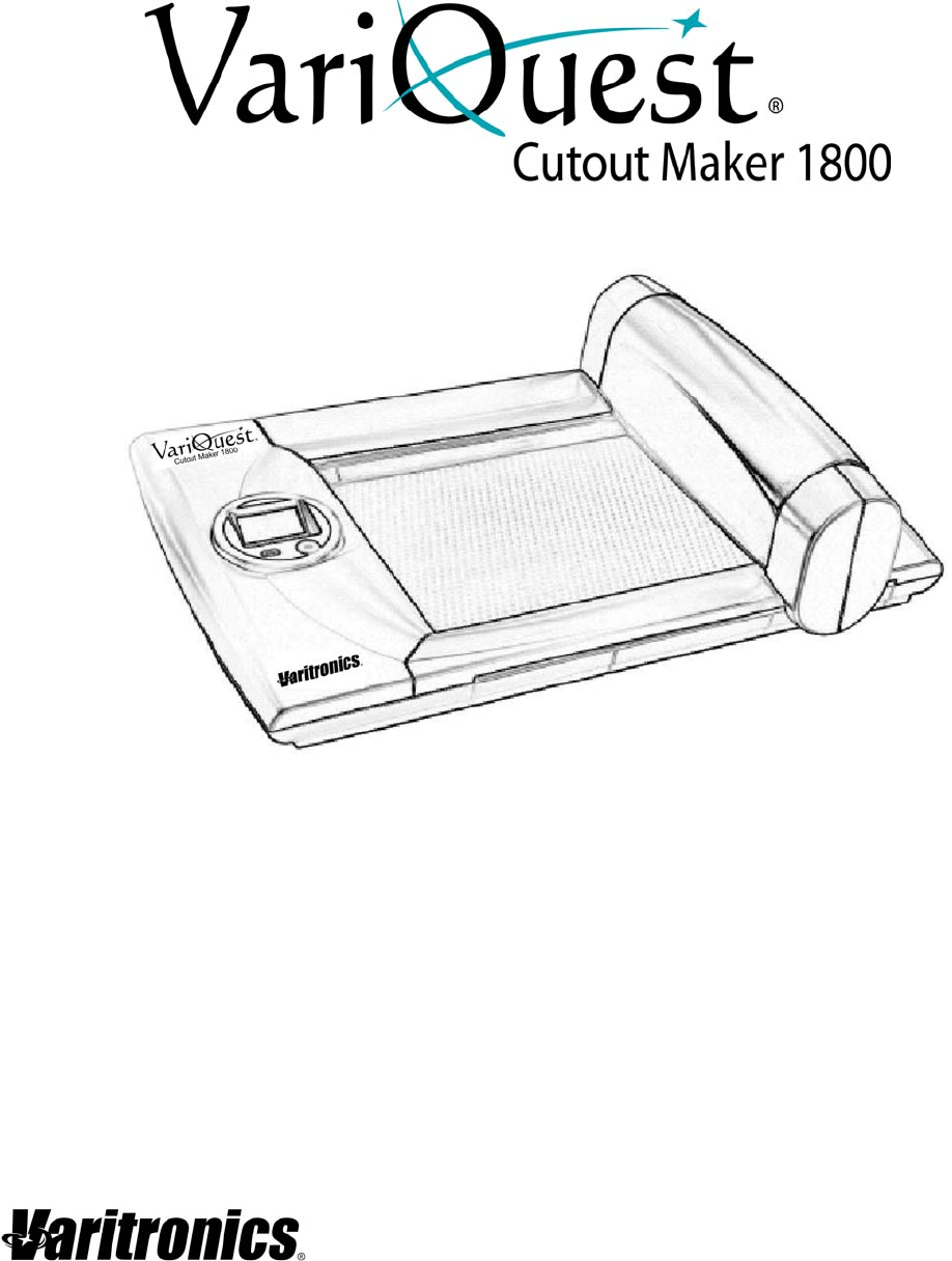
User’s Guide www.variquest.
Copyright Copyright This manual is copyrighted with all rights reserved. No portion of this manual may be copied or reproduced by any means without the prior consent of Varitronics, LLC. While every precaution has been taken in preparation of this document, Varitronics assumes no liability to any party for any loss or damage caused by errors or omissions or by statements resulting from negligence, accident or any other cause.
Standard Warranty Standard Warranty Varitronics, LLC warrants the equipment and accessories comprising the VariQuest® Cutout Maker 1800 will be free from defects in material and workmanship for one (1) year from the date of customer purchase. Original serial number must appear on product. Removal of serial numbers will void this warranty and any equipment and accessories that have been altered or modified in any way and are not as originally purchased will void this warranty.
Safety Information Warning Symbols Safety Information The instructions in this manual have been labeled with various types of caution and warning messages. The symbols preceding these messages indicate information that must be followed to avoid damage to property or injury to users of the Cutout Maker or people in the vicinity of the Cutout Maker.
Safety Information Warning Symbols Warning • • • Always hold the plug firmly when removing it from the power socket. Do not simply pull on the cord. Pulling on the cord to remove the plug from the power socket or applying excessive force when doing so may damage the cord, which may in turn result in fire or electrical shock. If the Cutout Maker overheats, emits smoke, or gives off an unusual odor, turn off the power switch immediately and remove the plug from the power socket.
This page is intentionally left blank.
Contents Copyright ....................................................................................................................ii Trademarks .................................................................................................................ii Standard Warranty ....................................................................................................iii Safety Information ....................................................................................................
5 - Maintenance Maintenance Summary .......................................................................................... 5-1 Replacing the Cutting Blade .............................................................................. 5-2 Replacing the Cutting Mat ................................................................................. 5-6 Oil Gantry Rails ............................................................................................... 5-10 Clean Tip Sensor .......................
1 Features, Accessories and Materials This chapter provides an overview of the VariQuest® Cutout Maker 1800 features, accessories and materials.
Features Features • The Cutout Maker is designed to allow even first-time users to quickly produce high quality cutout shapes from sheets of construction paper, cold laminated construction paper, card stock, bond paper, VariQuest® Vinyl Sheets and VariQuest® Magnetic Sheets. • You can easily create single or multiple cutouts using the VariQuest® Design Center Software.
System Accessories System Accessories The Cutout Maker comes with a Starter Maintenance Kit that contains: • Blades (3-pack) • Blade/Chad Removal Tool • Tweezers VariQuest® Cutout Maker 1800 User’s Guide 1-3
Materials Classifications for Unspecified Paper Types Materials CAUTION! Use of material other than that specified for use with the Cutout Maker may result in poor cut quality and damage to the blade. There is no direct correlation between paper weight and the classification of paper as “light weight” or “heavy weight” among manufacturers of construction paper. Due to the large variation of paper classifications, VariQuest® Cutout Maker paper is defined below.
2 Components and Specifications This chapter shows the locations of the major VariQuest® Cutout Maker 1800 components and provides detailed system specifications.
Components Gantry Cover Open Components Perspective View 1 2 3 Gantry Cover Open 4 No.
Components Side View Side View 4 1 2 No.
Components Control Panel Control Panel The control panel provides buttons to manually start and stop cutter operation. Pressing the GO button starts the cutter when all of the software selections are completed and the LCD display indicates a "Ready" condition exists. • Pressing STOP retracts the cutter blade and pauses the cutter operation. • Pressing GO restarts the cutter operation from the point at which it paused.
Specifications Control Panel Specifications Cutout Maker 1800 Technical Data Sheet Output • Maximum cutout size: 11-1/2” x 17-1/2”; up to 2’ x 3’ when tiling • Minimum scrap size: 4” x 6” (101.6 mm x 152.4 mm) Machine • Display: 4 line, 16 characters LCD graphical display • Cutting speed: up to 6” per second (simple shapes) • USB port: 1 • Dimensions: 33” W x 21.5” D x 12.5” H • Weight (machine only): 41.
3 Getting Started This chapter provides instructions for unpacking and setting up the VariQuest® Cutout Maker 1800. Keep this guide near the Cutout Maker so it can be available for reference.
Unpacking and Positioning Unpacking the Cutout Maker Unpacking and Positioning Unpacking the Cutout Maker The Cutout Maker and accessories are packed in a cardboard carton with foam padding for protection during shipment. Carefully unpack the items and keep the packing materials. If you need to ship the Cutout Maker in the future, repack the system as shown in the figure. WARNING Due to the weight of the unit, we recommend that 2 people lift the Cutout Maker from the carton.
Unpacking and Positioning Verifying Packaging Contents Verifying Packaging Contents After unpacking, verify that all of the following items have been included in the Cutout Maker box: 1 2 3 4 No.
Unpacking and Positioning Positioning the Cutout Maker Positioning the Cutout Maker To ensure proper functioning of the Cutout Maker on a work space, allow adequate space around the system as shown below. 2 in. / 51 mm 2 in. / 51 mm 2 in. / 51 mm 2 in.
Setting up the Cutout Maker Connecting the Power Cord Setting up the Cutout Maker Connecting the Power Cord WARNING Never operate the Cutout Maker in an area where it can get wet CAUTION! Always connect the power cord to the Cutout Maker before inserting the plug into a wall socket Connect the power cord to the Cutout Maker. Then insert the power plug into a grounded three-prong wall socket. 1. Set the power switch to its “0” (OFF) position. 2.
Connecting the Cutout Maker Connecting to a VariQuest® Design Center Connecting the Cutout Maker Important Use the USB cable supplied with the Cutout Maker to connect to the VariQuest® Design Center or a PC. The USB cable complies with FCC “Rules and Regulations,” Part 15 for Class A Equipment using fully-shielded six-foot data cables. Use of longer cables or unshielded cables may increase radiation emissions above the Class A limits.
Connecting the Cutout Maker Connecting to a Personal Computer Connecting to a Personal Computer The Cutout Maker provides a standard interface for connecting to a computer (USB connector). Connect one end of the cable provided to an available USB connector on the computer, and connect the remaining end to the USB connector on the Cutout Maker. Power on the Cutout Maker and the computer, and install the VariQuest® Design Center Software.
4 Operating the Cutout Maker This chapter provides instructions for operating the Cutout Maker.
Loading Material Loading Material Before loading material on the VariQuest® Cutout Maker 1800, you must choose the appropriate material type in the VariQuest® Design Center Software. This software is installed on the VariQuest® Design Center or on your PC. When you select the material type in the software, the Cutout Maker adjusts the output settings (blade depth, force and cutting speed) accordingly.
Typical Operating Sequence Operating Example Typical Operating Sequence Important The VariQuest® Cutout Maker 1800 can be used only with the VariQuest® Design Center Software. The VariQuest® Design Center Software is installed on your VariQuest® Design Center or PC. Refer to the separate VariQuest® Design Center User’s Guide for software installation.
Typical Operating Sequence Operating Example To smooth paper/start cut job: 1. Smooth the paper on the cutting mat. Note: Smoothing paper on the cutting mat ensures a clean cut. 2. Press GO to start the cut job. Once cutting is complete, you can remove your cutout from the cutting bed.
5 Maintenance This chapter describes the periodic maintenance procedures required during normal operation of the Cutout Maker.
Maintenance Summary Replacing the Cutting Blade Replacing the Cutting Blade 1. Set the power switch [1] to 0 (OFF) to turn the machine off. 1 2. Open the gantry top cover [2a], locate the blade holder/motor assembly [2b] and move it toward the middle of the gantry track. 2a 2b 3. Rotate the blade holder [3] 90° towards the front of the unit to gain access to the blade.
Maintenance Summary Replacing the Cutting Blade 4. Press blade release button [4a] at the rear of the blade holder to expose the blade. CAUTION! The cutter blade protrudes from the blade holder [4b] slightly even when retracted. Take care to avoid contact with the blade. Personal injury or equipment damage may result if the blade is touched. 4b 4a 5. Press the blade removal tool [5], included in maintenance kit, over the blade and remove the blade from the blade holder.
Maintenance Summary Replacing the Cutting Blade 6. Carefully position the blade in the blade holder [6] and insert it until only 1/4 inch of the blade protrudes from the holder. CAUTION! The cutter blade protrudes from the blade holder slightly even when retracted. Take care to avoid contact with the blade. Personal injury or equipment damage may result if the blade is touched. 6 7.
Maintenance Summary Replacing the Cutting Blade 8. Rotate the blade holder assembly 90° [8a] back to its operating position [8b]. 8a 8b 9. Close the gantry top cover [9] on the Cutout Maker.
Maintenance Summary Replacing the Cutting Mat Replacing the Cutting Mat 1. Set the power switch [1] to 0 (OFF) to turn the machine off. 1 2. Slide the gantry forward [2a] and grasp the rear edge of the cutting mat. Slide the mat out (to rear) [2b] from between the channels on each side of the bed [2c].
Maintenance Summary Replacing the Cutting Mat 3. With the gantry moved forward [3a], position the cutting mat soft side up [3b] so that the sides of the mat protrude into the channels on each side of the bed [3c]. 3b 3a 3c 4. Guide the cutting mat forward between the channels [4] on each side of the bed.
Maintenance Summary Replacing the Cutting Mat 5. Continue sliding the mat forward until the guide slots [5a] on the leading edge of the mat are fully engaged with the guides on the front end of the bed [5b]. 5a 5b 6. With the leading edge of the mat secured, align the notches on the rear edge of the mat with the guide posts on the bed [6]. Press the mat down to secure it in position.
Maintenance Summary Replacing the Cutting Mat 7. Turn the machine on. 8. Ensure that the gantry returns to the home position [8]. 8 Note: In some cases, you may rotate the protective mat to make use of surface area that is not worn. Either end of the mat may be inserted into the Cutout Maker.
Maintenance Summary Oil Gantry Rails Oil Gantry Rails 1. Lift gantry top cover [1]. 1 2. Apply a small amount of general household oil (such as 3-in-1 oil) to a clean cloth and wipe on exposed edge of upper [2a] and lower [2b] gantry rails. Note: Take care not to apply too much oil. Oil should not drip or pool. Remove excess oil with a clean cloth. 2a 2b 3. Close gantry top cover.
Maintenance Summary Clean Tip Sensor Clean Tip Sensor 1. Check that there are no obstructions, residue or paper debris covering the tip sensor. 2. Using the tweezers and chad removal tool from the maintenance kit, remove any debris from the tip sensor location plunger. 3. Remove any adhesive ooze from the tip-sensor area with a swab and isopropyl alcohol.
6 Troubleshooting This chapter describes how to locate and solve problems that you may encounter while using the Cutout Maker. The following information is contained in this chapter: • “Process” on page 6-1 • “Troubleshooting” on page 6-2 • “Error Codes” on page 6-4 • “Servicing the Cutout Maker” on page 6-6 Process Many problems can be traced to something as simple as a loose connection. Check the following before proceeding to the problem-specific solutions on the next page.
Troubleshooting Tips Troubleshooting Diagnosis Cutout Maker does not work even though the power switch has been turned on. LCD Display does not turn on. Excessively loud noise. Note: In each of the following cases, follow the 5 steps shown in the “Required Action” column. • Troubleshooting Required Action 1. Verify that power cord has been plugged in properly. 2. Verify that power switch is turned on. 1. Verify that power cord has been plugged in properly. 2. Verify that power switch is turned on. 1.
Troubleshooting Tips Diagnosis Troubleshooting (Continued) Required Action Paper scrunching during cutting. Paper moves while cutting. 1. Adjust the cutting blade depth 1 step negative (see “Loading Material” on page 4-2). 2. Try cutting again. If condition persists, repeat step 1. 3. Clean tip sensor. See “Clean Tip Sensor” on page 5-11. 1. Mat is dirty, clean with isopropyl alcohol. 2. Scrap paper is too small, use larger scrap paper. Note: Smaller scrap sizes may move on the cutting mat.
Error Codes Tips Error Codes The following table describes the Error Codes that may appear on the control panel and corrective action required to correct the problem. Note: Error codes contain a 2nd digit that the user does not have to be concerned with. Error Codes Message Displayed Cutter stalled. Check mat for obstructions. Press stop to clear error. Error #3 or Error #4 Corrective Action 1. Verify that there are no obstructions on the mat. 2. Insert new material. 3.
Error Codes Tips Message Displayed Cut speed error. Select a different object size and try again. Press stop to clear error. Error Codes (Continued) Corrective Action 1. Select a different object size in the VariQuest® Software on the Design Center touch computer or the PC. 2. Press STOP to clear error. 3. Try again. 4. If the error persists, contact your VariQuest® dealer. Error #11 Cutter head failed to lift. 1. Press STOP to clear error. Press stop to clear error. 2. Try again. Error #14 3.
Servicing the Cutout Maker Tips Servicing the Cutout Maker If you are unable to solve the problem, you need to have the Cutout Maker serviced. To service your Cutout Maker: 1. Write a description of the problem and a checklist of the steps you took when trying to fix the problem. This information may be useful to the service personnel. 2. Contact your VariQuest® dealer for further instructions. 3. If instructed to do so by your VariQuest® dealer, pack the Cutout Maker in the original carton.
© 2012 Varitronics, LLC All Rights Reserved.