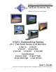
Solutions for Demanding Applications VarTech Systems Inc. Industrial CRT and Flat Panel Displays VT201 DiamondVue Series 20.1” Flat Panel Series LCD Monitors VT201C · VT201R VT201P · VT201PSS VT201W · VT201M · VT201MF Transflectives: VT201CTSR · VT201PTSR VT201PSSTSR · VT201RTSR User’s Guide Read these instructions completely before attempting to operate your new Color Display.
Table Of Contents Page Section 1 Page Section 4 Introduction 1 Touch screen 10 1.1 About LCD Monitors 1 4.1 Introduction 10 1.2 Product Safety Precautions 2 4.2 Installation 10 Section 2 Section 5 Display Setup 3 Display Features 3 2.1 Unpacking The Display 4 Section 6 2.2 Included Parts 4 Cleaning & Maintenance 2.3 Connecting Your Display 4 2.4 Signal Connections 4-5 Section 3 Troubleshooting Tips 11-12 13 Section 7 Mechanical Drawings 14 7.
Section 1 INTRODUCTION About LCD Monitors 1.1 What you gain by using an LCD monitor in your industrial controls LCDs are the future of display technology. CRTs although they have dropped in cost significantly, do not offer the performance, reliability, and mounting options available with LCDs. LCD monitors consist primarily of an LCD, Video Board and a Back Light video. The LCD determines to a large extent the viewing angle, brightness and contrast.
1.2 Product Safety Precautions Ensure that sufficient space is available around the display to provide the circulation necessary for cooling. Ensure that the ambient air temperature will not exceed the specified maximum temperature. Do not attempt to service this display yourself. The rear chassis has a seal so that non qualified personal will not expose themselves to dangerous voltages or other risks.
Section 2 DISPLAY SETUP 2.1 VT201 Series Display Features Capable of displaying unlimited colors in a continuous spectrum. The high contrast LCD enhances the image with no geometric distortion. The VT201 DiamondVue Series directly accepts an analog 5 wire RGB with separate H/V sync or 4 wire RGB with separate combined sync or 3 wire SOG. The VT201 DiamondVue Series is auto synchronous adjusting the display to the appropriate input between VGA, SVGA,XGA, and SXGA.
2.2 Unpacking and setting up your display Your LCD monitor package will consist of the components listed below. Open shipping container and lay all components on a flat clean surface. 2.3 What is included with your display VT201C, VT201P, VT201P-SS, VT201R, VT201MF, VT201W, VT201M LCD Monitor or VT201CTSR, VT201PTSR, VT201PSSTSR, VT201RTSR Transflective 5 ft Video Cable 10-32 Mounting Hardware.
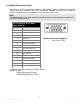
2.5 Signal Connections Cont. You can use an HD-15 connector cable or a BNC adapter cable to connect the flat panel monitor to the host computer. The HD-15 video cable (supplied in the kit) you use with this monitor is equipped with a conventional HD-15 connector at each end. Note: The following figure is the view looking into the pin end of the male connector or solder term end of the female connector. Pin assignments for the HD15 video connector.
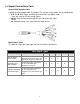
2.5 Signal Connections Cont. Optional BNC Adaptor Cable A 5BNC-to-HD15 adapter cable is available. The functions of the cables are described below. R, B, and G: Red, Green, and Blue input connectors to establish color. These are used for RS-343 analog signals. HS/CS: Separate horizontal/composite sync signal from the video source. VS: Separate vertical sync signal from the video source.
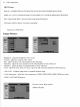
Section 3 GETTING STARTED 3.1 Adjusting the display The VT201 DiamondVue Series display has an embedded microprocessor in the converter card. Once you have the unit displaying the resolution you desire for your application do the following: In order to navigate to the appropriate adjustments, press Menu and the OSD layout chart will appear as indicated as shown below. Vartech Systems, Inc Menu Select Down Up Input 3.
Section 4 4.1 TOUCH SCREEN Introduction Touch screens are a common means to interface operator inputs to a system. The universal standard of Windows GUI (Graphical User Interface) has significantly increased the use of touch screens. There are four main touch technologies. The technologies are resistive, surface acoustic wave (SAW), capacitive, and infrared (IR). Each touch technology has advantages and disadvantages based on different user applications. 4.
Section 5 TROUBLESHOOTING Troubleshooting Trouble No Picture Troubleshooting Tip The signal cable should be properly connected to the display card and computer. Try disconnecting the video cable from the display and connecting to a CRT display if available to confirm the presence of proper video. Make sure power is connected to the proper DC or AC source. Make sure the resolution mode is supported by the display and check settings of the display card.
Troubleshooting Cont. Trouble Troubleshooting Tip Screen is blank. Screen saver activated. Video Cable problem. Check for proper installation Change video cable . Faulty video display. Needs Service. Image is dim, even with brightness and contrast controls set full UP Video cable problem. Check for proper installation of cables Faulty video source. Faulty display. Image not centered Reset the horizontal and vertical positioning using the on-screen menu.
Section 6 CLEANING AND MAINTANENCE Cleaning Occasionally clean the display panel and cabinet with a soft cloth dampened (not soaked) with a mild (non-abrasive) glass cleaner. Keep turning a fresh side of the cloth toward the screen surface to avoid scratching it with accumulated grit. Note: The solvent should be applied only to the cloth, and not directly on the monitor screen. Do not use paper products as they may scratch the surface. To minimize the risk of abrasion, allow the screen to stand dry.
Section 7 MOUNTING INSTRUCTIONS Mechanical Drawings Model Description VT201C 20.1” DiamondVue Chassis Mount Mechanical Drawing 15-18 VT201P 20.1” DiamondVue Panel Mount Mechanical Drawing 19-20 VT201R 20.1” DiamondVue Rack Mount Mechanical Drawing 21 VT201W 20.1” DiamondVue Wall Mount Mechanical Drawing VT201MF 20.1” Foxboro Configured Mechanical Drawing 7.1 Page(s) 22 Panel Mount Procedure Panel Mounting Procedure 1. Cut and drill the panel (refer to panel mount drawing).
Section 8 SPECIFICATIONS ENGINEERING SPECIFICATIONS Panel Size 20.1” Type Active Matrix Color Thin Film Transistor (TFT) Resolution Capabilities VGA to UXGA Pixel Pitch .3075 mm Active Display Area 16.21” x 12.20” 411.7mm x 309.8mm Pixel Format 640 x 480, 800 x 600, 1024 x 768, 1280 x 1024, 1600 x 1200 Viewing Angle (Left/Right) 80/80 deg. Viewing Angle (Up/Down) 80/80 deg.
VARTECH SYSTEMS HEADQUARTERS 11529 Sun Belt Ct. Baton Rouge, Louisiana 70809 Toll-Free: 800.223.8050 International Phone: 001.225.298.0300 Fax: 225.297.2440 E-mail: sales@vartechsystems.com www.vartechsystems.com 150-021-015 3.15.