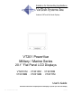
Solutions for Demanding Applications VarTech Systems Inc. Industrial CRT and Flat Panel Displays VT201 PowerVue Military / Marine Series 20.1” Flat Panel LCD Displays VT201CM · VT201PM · VT201RM VT201MM · VT201WM · VT201YM User’s Guide Read these instructions completely before attempting to operate your new Color Display. 20.
Table Of Contents Section 1 Page Introduction Section 4 Page Touch screen Unpacking 1 Touch Screen Introduction Checking Package Contents 1 Touch Screen Definition Product Safety Precautions 2 Touch Screen Serial Interface 18 On Safety 2 Setting up the Touch Interface 18 On Installation 3 Installing Windows NT 4.
Section INTRODUCTION 1 1.1 UNPACKING Before unpacking, the shipping carton should be inspected for damage. Then, the carton should be carefully opened and the monitor removed. The monitor itself should be carefully inspected for shipping damage. If damage has occurred, the shipping carton and all packing materi-als should be saved for possible inspection by the shipping company, and the shipping company and VarTech should be notified immediately.
1.3 Product Safety Precautions This unit has been engineered and manufactured to ensure your personal safety, however improper use may result in potential electrical shock or fire hazards. In order to allow the proper operation of all safeguards incorporated in this display, observe the following basic rules for its installation, use, and servicing. 1.4 On Safety Use only the power cord supplied with the unit.
1.5 On Installation Do not allow anything to rest upon or roll over the power cord, and do not place the display where the power cord is subject to damage. Do not use this display near water such as near a sink, in a wet location where there is standing water. Displays are provided with ventilation openings in the cabinet to allow the release of heat generated during operation. If these openings are blocked, built-up heat can cause failures which may result in a fire hazard.
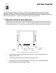
Section DISPLAY SETUP 2 2.1 2.2 VT201 Military/Marine Series Display Features ⇒ Capable of displaying unlimited colors in a continuous spectrum. The high contrast LCD enhances the image with no geometric distortion. ⇒ The VT201 Military / Marine Series directly accepts an analog 5 wire RGB with separate H/V sync or 4 wire RGB with separate combined sync or 3 wire SOG. ⇒ The VT201 Military / Marine Series is auto synchronous adjusting the display to the appropriate input between VGA, SVGA, and XGA.
2.4 Connecting the Display When connecting the monitor to an analog signal source, it is necessary to use a cable that terminates on the monitor end with an HD-15 connector that mates to the monitor’s connector, and on the source end with an HD-15 connector or with some combination of three to five BNC connectors, as appropriate to the source.
2.5 Signal Connections Cont. Optional Video Cable Options HD15 to HD15 This cable should be used when connecting the monitor to a signal source that provides analog RGB outputs by way of an HD-15 connector. HD-15 to 5 BNC This cable should be used when connecting the monitor to an analog source that provides RGB video by way of BNC connectors. There are three possible wiring schemes, depending on the type of sync supplied by the source. The DVI-I to BNC cable can be used with all three schemes.
2.6 Power and Ground Connections AC Power A monitor equipped for operation on AC power should be connected to a single-phase power source providing 115 to 230VAC nominal (85 to 264VAC) at 47 to 66Hz, or 400Hz. Connection is made by way of an IEC power cord at the monitor’s power input connector, or by way of a military style connector, when that option is specified.
GETTING STARTED Section 3 The monitor is pre-aligned at the factory. However, minor adjustments are usually necessary following installation to optimize the monitor’s performance with a particular video source and particular video formats. This section of the manual describes the operator accessible controls that allow for such adjustment. It goes on to describe a typical setup procedure. 3.
3.2 Setting up the Video Source The monitor can be adjusted to display a wide range of video formats, depending on the capabilities of the video source (typically a PC graphics card) and the requirements of the application. Once adjustments have been made for a given format, they are remembered, and readjustment is automatic when switching between remembered formats.
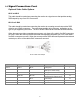
3.2 Setting up the Video Source Cont. The following table provides a good guideline for estimating the capabilities of a given video source or for determining the memory requirements for a new source. Video RAM Requirements for Various Display Resolutions and Color Depths* Color Depth / Resolution 256 colors (8 bpp) 65536 colors (16 bpp) 16777216 colors (24 bpp) 640x480 0.5MB 1.0MB 1.0MB 800x600 0.5MB 1.0MB 1.5MB 1024x768 1.0MB 1.5MB 2.5MB 1152x864 1.0MB 2.0MB 3.0MB 1280x1024 1.
3.3 Adjusting the Monitor For details about navigating the OSD menu system, see the following section. This section discusses the use of the OSD menus to optimize the monitor for display of a given video format. An initial adjustment of the monitor should first be made by pressing the AUTO button. Afterwards, if additional adjustment is thought to be necessary, the following procedure can be used. 1. Set scaling mode. Press any one of the Up/Down/Right/Left buttons to bring up the Quick Menu.
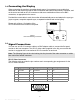
3.4 Navigating the OSD in detail The integrated On-Screen Display (OSD) is used to control various display and system parameters. The OSD provides a system of setup menus that are accessed with the controls shown below. SOURCE MENU DOWN UP LEFT RIGHT AUTO Figure 3 – OSD Controls Button Use SOURCE (EXIT) The first button press displays the current source.
3.5 Picture Submenu The Picture submenu presents a list of items that depends on the selected video source (digital, analog RGB, S-video, or composite video). The current version of the product supports only an analog RGB source.
3.6 OSD Submenu The OSD submenu contains the following functions: Navigation Buttons Menu Item Explanation H Pos Note that H POS and V POS refer to the position on the screen of the OSD itself, not to the position of the image from an external source. V Pos UP OSD Timeout The OSD TIMEOUT period is the time the OSD will remain on the screen in the absence of user input. If there is no user input for the duration of the timeout period, the OSD will disappear.
3.7 Utility Submenu The Utility submenu contains the following functions: Navigation Buttons Menu Item Explanation Freeze Frame This selection is used to “capture” the image content currently being displayed. Updates of the display based on subsequent signal changes at the video inputs are temporarily halted. This control could be useful, for example, in conjunction with a Print Screen operation. Reset Select with caution.
3.8 Quick Menu The Utility submenu contains the following functions: Navigation Buttons Menu Item Explanation Brightness On a CRT monitor, the brightness control is really a black level adjustment and is set so that the background raster is just cut off when a black screen is displayed. On an LCD monitor, the brightness control is a control of the backlight luminance level. Both black and white levels change with changes in backlight luminance.
TOUCHSCREEN Section 4 4.1 Touch Screen Introduction Touch screen interfaces have become the standard interface in the past 5 years. They are, rugged, reliable, extremely flexible and easier than ever to implement! Over 90% of the display packages Vartech Systems builds are touch screen systems. If you are uncertain about using a touch screen, or are having difficulty, please call us.
4.2 Touch Screen Definition Cont. Connecting the touch screen 1. Make sure all optional cables have been received. 2. Connect one end of the 6 foot touch screen serial cable to the touch screen port D9 connector on the side of the monitor. 3. Connect the other end to any communications port on the host computer. 4. Tighten the captive screws on the cable connector to secure it. 4.
4.5 Installing Touch Screen Driver Windows NT 4.0 1. Start your computer. 2. Insert the MonitorMouse for Windows NT disk into drive A. 3. Click the Start button then click Run. 4. Type “a:\setup” in the space provided and press Enter. 5. Follow the directions on the screen. 6. MonitorMouse for Windows NT provides two Installation options. Most users should select Typical (the default) and click Next to continue. Custom allows you to install the sample touch screen programming files. 7.
4.7 Installing Touch Screen Driver Windows 2000 1. Start your computer. 2. Insert the MonitorMouse for Windows 2000 disk into drive A. 3. Click the Start button then click Run. 4. Type “a:\setup” in the space provided and press Enter. 5. Follow the directions on the screen. 6. MonitorMouse for Windows 2000 provides two Installation options. Most users should select Typical (the default) and click Next to continue. Custom allows you to install the sample touch screen programming files. 7.
TROUBLESHOOTING TIPS Section 5 Front panel power • indicator does not come on • when power switch is set to “on” position. • Check for a loose, damaged, or disconnected power cord. Check for power available at the AC receptacle. (Plug in a known good lamp.) Check the monitor’s AC fuse. (Refer to the section below on fuse replacement.) Monitor is powered on, but • has no display • Check for a loose, damaged, or disconnected power cord. Ensure that the luminance control is not turned all the way down.
Section 6 CLEANING AND MAINTENANCE Cleaning Occasionally clean the display panel and cabinet with a soft cloth dampened (not soaked) with a mild (non-abrasive) glass cleaner. Keep turning a fresh side of the cloth toward the screen surface to avoid scratching it with accumulated grit. Note: The solvent (a 50/50 mixture isopropyl alcohol and water) should be applied only to the cloth, and not directly on the monitor screen. Do not use paper products as they may scratch the surface.
Section MECHANICAL DRAWINGS 7 Mechanical Drawing Description Page VT201PM 20.1” PowerVue Panel Mount 25 VT201RM 20.1” PowerVue Rack Mount 26 7.1 Console or Panel Mounting The VT201 monitors are designed for mounting on a console panel. Before installing the monitor on a panel, ensure that the following conditions for installation are met: • Adequate ventilation must be available within the console to ensure that monitor is not exposed to ambient temperatures above 50°C.
7.2 VESA Arm or Yoke Mounting The VT201 monitors are designed for mounting to an articulated arm that provides a mounting flange with a VESA standard hole pattern. Please refer to mounting instructions supplied with the VESA arm to be used. 7.3 Rack Mounting The VT201 monitors are designed to be mounted without slides in an EIA 19” rack cabinet. The hole pattern on the monitor’s front panel allows mounting the unit on rack rails that have either a “Wide” or a “Universal” hole pattern.
25 20.
26
Section SPECIFICATIONS 8 SPECIFICATIONS Panel Size 20.1” Type TFT Active matrix w/ Anti-Glare coating Pixel Pitch 0.255mm Max. Resolution Viewing Angle (Up/Down) 1600 x 1200 16.06” x 12.04” 408.0mm x 306.0mm 640 x 480, 800 x 600, 1024 x 768,1280 x 1024, 1600 x 1200 80/80º Viewing Angle (Left/Right) 80/80º Contrast Ratio TBD Brightness 250 Nits Response Time TR = 5ms TD = 20ms Active Screen Area Pixel Format Back Lights Video Input Cold Cathode 50,000 Hrs.
VARTECH SYSTEMS HEADQUARTERS 11529 Sun Belt Ct. Baton Rouge, Louisiana 70809 Toll-Free: 800.223.8050 International Phone: 001.225.298.0300 Fax: 225.297.2440 E-mail: sales@vartechsystems.com www.vartechsystems.com 150-055-001 12.15.