DEC 7000 AXP System VAX 7000 Console Reference Manual Order Number EK–70C0B–TM.002 This manual is intended for the system manager or system operator and covers the console commands for the DEC 7000 and VAX 7000 systems.
First Printing, November 1992 The information in this document is subject to change without notice and should not be construed as a commitment by Digital Equipment Corporation. Digital Equipment Corporation assumes no responsibility for any errors that may appear in this document. The software, if any, described in this document is furnished under a license and may be used or copied only in accordance with the terms of such license.
Contents Preface ........................................................................................ Chapter 1 Console Hardware 1.1 1.2 1.3 Processor Console Hardware ..................................... System Controls and Connections .......................... Primary and Secondary Processors ......................... Chapter 2 Console User Interface 2.1 2.2 2.3 2.4 Command Syntax .....................................................
3.15 3.16 3.17 3.18 3.19 3.20 3.21 3.22 3.23 3.24 3.25 3.26 3.27 3.28 3.29 3.30 3.31 3.32 Repeat ....................................................................... Set Configuration ..................................................... Set EEPROM ............................................................ Set .............................................................. Set Host ....................................................................
Example 3-18 Example 3-19 Example 3-20 Example 3-21 Example 3-22 Example 3-23 Example 3-24 Example 3-25 Example 3-26 Example 3-27 Example 3-28 Example 3-29 Example 3-30 Example 3-31 Example 3-32 Set ....................................................................... 3-30 Set Host Command ............................................... Set Power Command ............................................. Show Configuration Command ............................
vi
Preface Intended Audience This manual is written for the system manager or system operator. Document Structure This manual uses a structured documentation design. Topics are organized into small sections for efficient on-line and printed reference. Each topic begins with an abstract. You can quickly gain a comprehensive overview by reading only the abstracts. Next is an illustration or example, which also provides quick reference. Last in the structure are descriptive text and syntax definitions.
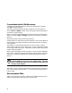
Conventions Used in This Document Commands and command options are printed in bold type; for example, The help command displays .... Although commands and environment variables are not case sensitive (that is, Boot and BOOt are both valid), commands and command options are shown in lowercase type. When a command may be abbreviated, the portion that may be omitted is shown in brackets: -flags or -fl[ags]. Brackets also indicate an element is optional. Braces ({}) indicate a choice from the enclosed list.
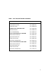
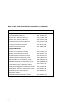
Table 1 DEC 7000/VAX 7000 Documentation Title Order Number Installation Kit EK–7000B–DK Site Preparation Guide EK–7000B–SP Installation Guide EK–700EB–IN Hardware User Information Kit EK–7001B–DK Operations Manual EK–7000B–OP Basic Troubleshooting EK–7000B–TS Service Information Kit—VAX 7000 EK–7002A–DK Platform Service Manual EK–7000A–SV System Service Manual EK–7002A–SV Pocket Service Guide EK–7000A–PG Advanced Troubleshooting EK–7001A–TS Service Information Kit—DEC 7000 EK–7002B–
Table 1 DEC 7000/VAX 7000 Documentation (Continued) Title Order Number Reference Manuals Console Reference Manual EK–70C0B–TM KA7AA CPU Technical Manual EK–KA7AA–TM KN7AA CPU Technical Manual EK–KN7AA–TM MS7AA Memory Technical Manual EK–MS7AA–TM I/O System Technical Manual EK–70I0A–TM Platform Technical Manual EK–7000A–TM Upgrade Manuals x KA7AA CPU Installation Guide EK–KA7AA–IN KN7AA CPU Installation Guide EK–KN7AA–IN MS7AA Memory Installation Guide EK–MS7AA–IN KZMSA Adapter Installa
Table 2 Related Documents Title Order Number General Site Preparation Site Environmental Preparation Guide EK–CSEPG–MA System I/O Options BA350 DECstor/me Modular Storage Shelf Subsystem Configuration Guide EK–BA350–CG BA350 DECstor/me Modular Storage Shelf Subsystem User’s Guide EK–BA350–UG BA350-LA DECstor/me Modular Storage Shelf User’s Guide EK–350LA–UG CIXCD Interface User Guide EK–CIXCD–UG DEC FDDIcontroller 400 Installation/Problem Solving EK–DEMFA–IP DEC LANcontroller 400 Installation
Table 2 Related Documents (Continued) Title Order Number Operating System Manuals Alpha Architecture Reference Manual EY–L520E–DP DEC OSF/1 Guide to System Administration AA–PJU7A–TE DECnet for OpenVMS Network Management Utilities AA–PQYAA–TK Guide to Installing DEC OSF/1 AA–PS2DA–TE OpenVMS Alpha Version 1.
Chapter 1 Console Hardware This chapter describes how the console program and hardware function in DEC 7000 and VAX 7000 systems.
1.1 Processor Console Hardware The system processor module has several features dedicated to support of the console and diagnostic hardware. The following hardware provides console support: • 128-Kbyte flash-erasable programmable read-only memories (FEPROMs) hold the console program, diagnostic software, and bootstrap routines. • One 128-Kbyte FEPROM contains code that performs minimal initialization and testing functions required to bring up the console environment.
Figure 1-1 illustrates the system hardware. The console terminal is used for entering console commands. The console terminal is connected to the system through the console terminal port (shown in Figure 1-2). A printer, connected to the console terminal, provides a hardcopy record of console sessions. The console program is the software interface that translates console commands to the primary processor.
1.2 System Controls and Connections The system control panel consists of a keyswitch and three indicator lights. Three cable ports provide connections for expander cabinets and the console terminal. In a multiprocessor system, each processor has access to the console terminal line.
The control panel keyswitch (see Figure 1-2) has the following settings: Disable Removes 48 VDC power from the system. Power is still supplied to the cabinet control logic (CCL) module. Secure Prevents entry into console mode; position used while machine executes programs. Enable Allows entry into console mode; position used while machine executes programs. Restart A momentary switch position, used to reinitialize the system; causes self-test to start running.
1.3 Primary and Secondary Processors One processor is selected as the boot processor, and all other processors become secondary processors. This determination is made by the system at power-up or initialization and can be altered using console commands.
One processor in a multiprocessor system is designated as the primary processor. Since the primary processor performs the system bootstrap, it is also referred to as the boot processor. The lowest numbered enabled processor that has asserted its own boot processor bit is the boot processor. All console commands execute, by default, on the primary processor.
Chapter 2 Console User Interface This chapter describes the console program’s command language, console special characters, console environment variables, and device naming conventions. Console commands (see Chapter 3) allow you to boot the operating system, display the configuration, and verify the system. When the system is in console mode, the system is halted and the console firmware is executing.
2.1 Command Syntax The console command language has syntax rules for forming commands. Commands can contain up to 80 characters on a single line, can be abbreviated, and accept options. Numbers are in hexadecimal notation. Tabs and spaces are compressed. Table 2-1 Console Command Language Syntax Command Parameter Attribute or Action Length 80 characters maximum, unless the continuation character (\) is used. Case Upper- or lowercase characters are accepted.
Length: The console program accepts commands of up to 80 characters per line. This does not include the terminating carriage return or any characters deleted as the command is entered. A command longer than 80 characters, without the backslash character (see Section 2.2) causes the display of an error message. Case: Upper- or lowercase characters can be used for input. Characters are displayed in the case they are entered.
2.2 Console Special Characters The console program supports control characters, entered by holding down the Control (Ctrl) key and pressing the desired key, and other special characters. Table 2-2 Console Special Characters Character Function Return Backslash
Return terminates command line input. No action is taken on a command line until it is terminated by a carriage return. If no characters are entered and the Return key is pressed, it is treated as a null command. No action is taken, and the console prompts for input. Carriage return is echoed as carriage return, line feed. Backslash (\) allows continuation across lines from the terminal; must be the last character on the line to be continued.
Ctrl/R is echoed as ^R, followed by a carriage return, line feed, and printing the current command line. Deleted characters are omitted. This command is useful for hardcopy terminals. Ctrl/S suspends output to the console terminal until Ctrl/Q is entered. Ctrl/S is not echoed. Ctrl/U discards all characters that you entered on the current line. It is echoed as ^U, followed by a carriage return, line feed, and a new prompt. * allows wildcarding with device names and environment variables.
2.3 Console Environment Variables Console environment variables allow the user to modify the way the console commands operate. An environment variable is a name and value association maintained by the console program. The value associated with an environment variable is an ASCII string (up to 127 characters in length) or an integer. Certain environment variables are typically modified by the user to tailor the recovery behavior of the system on power-up and after system failures.
Table 2-3 Environment Variables (Continued) Variable Attribute Function bootdef_dev Nonvolatile The default device or device list from which booting is attempted when no device name is specified by the boot command. boot_file Nonvolatile The default file name used for the primary bootstrap when no file name is specified by the boot command, if appropriate.
Table 2-3 Environment Variables [Continued) Variable Attribute Function d_softerr Volatile Determines action taken following a soft error. Values are continue (default) and halt. Applies only when using the test command. dump_dev Nonvolatile Complete device specification of the device to which operating system dumps are written (if supported by the operating system). Default value is null. enable_audit Nonvolatile If set to on (default), enables the generation of audit trail messages.
2.4 Device Naming Conventions To use the console, the user needs to be familiar with the device names assigned by the system console. The system firmware assigns names to all supported CPUs, memories, I/O windows, I/O adapters, and end I/O devices in the system. The show configuration, show device, and show network commands (see Chapter 3) are used to obtain the assigned device mnemonics for all devices in the system.
The show network command displays all supported network boot devices (Ethernet and FDDI) and assigns a mnemonic to each (exa0.0.0.14.0, fxb0.0.0.4.1, for example). The device name for end I/O devices (disks, tapes, network devices, and so forth) is of the form: ddccuuuu.node.channel.slot.hose where the fields, described in Table 2-4, are separated by periods (.). Numbers in Table 2-4 are decimal.
Chapter 3 Console Commands Console commands provide the capabilities to examine and modify system state. Additionally, they allow tests to be directed to functional components of the system.
3.1 Boot The boot command boots the operating system. Example 3-1 Boot Command 1. >>> # Boot from local disk. >>> show device # Display I/O device information. polling for units on kfmsa0, slot 1, xmi0... dua2.2.0.1.0 R2TDYC$DIA2 RF73 polling for units on kdm700, slot 2, xmi1... dua1.0.0.2.1 DUA1 RA92 >>> boot dua2.2.0.1.0# # # # # # # # Boot device designations: du = device code. a = controller designation. 2 = device unit number. 2 = node number. 0 = device channel number. 1 = XMI slot number.
The boot command syntax is: b[oot] [-flags NNNN, M, PPPP] [-file ] where the -flags parameter allows additional boot command parameters N, M, and P. Specifying -fl[ags] overrides the boot_osflags environment variable (see Section 2.3). The NNNN flags, dependent on the system configuration, are used with OpenVMS VAX when booting from a shadow set. The M flag, dependent on the system configuration, specifies the system root of the boot device.
3. >>> >>> sh dev # Boot a system in a CI # VAXcluster. # Display I/O device information. polling for units on cixcd0, slot 2, xmi0... dua20.14.0.2.2 $100$DUA20 RA82 dua31.14.0.2.2 $100$DUA31 RA82 >>> boot -fl 0,4,0 dua20.14.0.2.2 # -fl[ags] indicates additional # command options follow. # 0 = not a shadow set boot # 4 = system root of boot device. # 0 = bootstrap loader options. # du = device code. # a = controller designation. # 20 = device unit number. # 14 = node number. # 0 = device channel number.
3.2 Build EEPROM The build eeprom command is used to create a new EEPROM image or to restore a corrupted EEPROM image. Example 3-2 Build EEPROM Command >>> build eeprom # Build EEPROM if invalid # message is displayed. Creating new EEPROM image System Serial Number> GAO1234567 Module Serial Number> SG226LFH01 # # # # # # Module Unified 2-5-2-4 Part Number> Module Firmware Revision> 1.
3.3 Cdp The cdp command performs basic configuration manageVAX 7000 ment of DSSI devices. Example 3-3 Cdp Command 1. >>> show device # Display I/O device # information. polling for units on kfmsa0, slot 0, xmi0... dua5.0.0.13.0 BASHFL$DIA5 RF71 polling for units on cixcd0, slot 14, xmi1... dub44.1.0.13.1 $1$DIA44 (BLANK4) RF71 >>> cdp -i dua.5.0.0.13.0: # -i entered to select # interactive mode - set all # parameters; no changes made. Node Name [BASHFL]? Allocation Class [0]? Unit Number [5]? dub44.1.
The cdp command syntax is: cdp [-{a,i,n,o,u}] [-sn] [-sa ] [dssi_device] where is allclass or unitnum, and dssi_device is the DSSI device. Table 3-1 summarizes the cdp command options. The cdp command permits the modification of DSSI device parameters from the console without explicit connection to a node’s DUP server. The parameters modified are the DUP task parameters nodename, allclass, and unitnum. Table 3-1 Cdp Command Options Option Function -a Sets device allocation class, allclass.
3.4 Clear EEPROM The clear eeprom command allows you to clear the selected EEPROM option. Example 3-4 Clear EEPROM Command >>> clear eeprom log # Clears all failure # information logged in # EEPROM. The clear eeprom command syntax is: cl[ear] ee[prom]
3.5 Clear Clear is used to remove an environment variable. Example 3-5 Clear >>> create fred fred set to # Create fred with null value >>> set fred "this is a string in an environment variable" fred set to this is a string in an environment variable >>> show fred fred this is a string in an environment variable >>> clear fred >>> show fred Environment variable not found >>> The clear removes an environment variable.
3.6 Clear Screen The clear screen command allows you to clear the terminal screen. Example 3-6 Clear Screen Command >>> clear screen # Refresh the terminal # screen. The clear screen command syntax is: cl[ear] sc[reen] There are no parameters or options.
3.7 Continue The continue command resumes processing at the point where it was interrupted by a Ctrl/P. Programs continue executing at the address currently in the program counter of the processor. Example 3-7 Continue Command $ ^P # VAX 7000 example # Stop processing on boot processor; # processor enters console mode. Console entry reason: ^P or Node Halt Entry PC: 80805442 Entry PSL: 041F8200 # System responds with message; system # has halted with 80805442 in the # program counter (PC).
The continue command syntax is: c[ontinue] Continue causes the primary processor to resume program mode, executing at the address currently in the program counter (PC). This address is the address that was in the PC when the primary processor received a Ctrl/P command. The system displays the hexadecimal PC value. When the boot processor receives a continue command, it does not perform processor initialization as it would for a boot procedure.
3.8 Crash The crash command causes the operating system to be restarted and generates a memory dump. Example 3-8 Crash Command P01>>> crash [operating system output appears] The crash command causes the operating system to be restarted in such a way as to force a crash. This allows the user to ^P a hung system and generate a memory dump. The crash command syntax is: cra[sh] There are no parameters or options. See the mchk command.
3.9 Create The create command allows you to create an environment variable. Example 3-9 Create Command 1. >>> create fred fred set to >>> show fred fred # Create a new environment # variable fred with a value # equal to null. 2. >>> create stuff 356 # Create a new environment # variable stuff with a value # equal to 356. 3. >>> create -nv delay # # # # Create a new nonvolatile environment variable delay in EEPROM with a value equal to null. 4. >>> create -nv work "dua44.0.0.4.
3.10 Deposit The deposit command stores data in a specified location. Example 3-10 Deposit Command 1. >>> dep -b -n 1FF pmem:0 0 # Clear first 512 bytes # of physical memory. 2. >>> d -l -n 3 vmem:1234 5 # Deposit 5 into four long# words starting at virtual # memory address 1234. 3. >>> d -n 8 R0 FFFFFFFF # Load GPRs R0 through R8 # with -1. 4. >>> d -1 -n 10 -s 200 pmem:0 8 # # # # 5. >>> d -1 pmem:0 0 >>> d + FF 6.
The deposit command syntax is: d[eposit] [-{b,w,l,q,o,h,u}] [-{n val, s val}] [space:]
where the options are values from Table 3-2, and is the value to be stored. If the specified value is too large to fit in the data size to be deposited, the console ignores the command and issues an error response. For data lengths longer than a longword, each longword of data should be separated by a space.space: is the optional device name (or address space) of the device to access (see Table 3-3), and address specifies the offset within a device to which data is deposited. Valid symbolic address forms (see Appendix A) include: • fpr-name, a symbol representing a floating-point register (DEC 7000 only). • gpr-name, a symbol representing a general purpose register. • ipr-name, a symbol representing the internal processor register. • PC, the program counter. The address space is set to GPR.
Table 3-3 Device Name and Address Space Options Option Device Name and Address Space Meaning Device name: xmi0, ka7aa1, demna0, and so forth. fpr Defines the address space as the floating-point register set, F0 through F31 (DEC 7000 only). gpr Defines the address space as the general register set, R0 through R15. ipr Defines the address space as the internal processor registers (IPRs). pt Defines the address space as the PAL temp register set, PT0 through PT31 (DEC 7000 only).
3.11 Examine The examine command displays the contents of a memory location, a register, or a device. The options are similar to the deposit command options. Example 3-11 Examine Command 1. >>> examine pc gpr: 000000F ( PC) 00000000 # Examine the program # counter - VAX 7000. 2. >>> examine sp gpr: 000000E ( SP) 00012FB8 # Examine the stack # pointer - VAX 7000. 3. >>> examine psl # Examine the processor # status longword # VAX 7000.
The examine command syntax is: e[xamine] [-{b,w,l,q,o,h,d,u}] [-{n val, s val}] [space:]
where the options are values from Table 3-4, space: is the optional device name (or address space) of the device to access, and address is a longword that specifies the first location to be examined. Appendix A lists the symbols recognized by the examine (and deposit) command.Examine uses most of the same options as deposit. Additionally, the examine command supports the -d option (instruction decode, which will disassemble the instructions at the current address). When using examine, if no options are given in subsequent commands, the system uses the options from the preceding commands as the defaults for address or location referenced, data type, including -d, (-b, -l, -w, and so forth), data size for increment (-s), and address space (gpr, ipr, pmem, and so forth).
3.12 Help The help command provides basic information on the console commands, when the system is in console mode. Example 3-12 Help Command 1. >>> help create # Display basic create command # information. Minimum # command input is highlighted. create [-nv] 2. >>> h examine examine[-{b,w,l,q,o,h,d,u}][-n val][-s val][space:]address -{b,w,l,q,o,h} ! data length -d ! decode instruction -n ! repeat count -s ! repeat address increment size -u ! protected mode 3.
3.13 Initialize The initialize command performs a reset. You can initialize the entire system or a specified device or subsystem. Example 3-13 Initialize Command >>> initialize demna0 The initialize command syntax is: i[nitialize] [] where is the name of the device or subsystem to be initialized. If specifies a memory module, you will receive a message stating that memory cannot be initialized, since the console runs from main memory. See Section 2.
3.14 Mchk The mchk command is used to dump internal state inforDEC 7000 mation to aid in the diagnosis of hardware failures. Example 3-14 Mchk command >> mchk V5.25-1/01.
The mchk command is typically used after a system crash to provide internal state information to aid in diagnosing hardware failures. The mchk command syntax is: mchk [n] where [n] is the LSB node id of the processor you are interested in. By default, you will get information from the primary processor.
3.15 Repeat The repeat command reexecutes the command that you pass as its argument until Ctrl/C is entered. Example 3-15 Repeat Command >>> repeat P 00000000 P 00000000 P 00000000 ^C >>> examine 00000000 EEEDFACC EEEDFACC EEEDFACC # Perform the specified # command until stopped # by Ctrl/C. The repeat command syntax is: r[epeat] [] where is the console command to repeat. To stop the repeat command, enter Ctrl/C.
3.16 Set Configuration The set configuration command records the current system configuration in EEPROM. Example 3-16 Set Configuration Command >>> set configuration The set configuration command syntax is: se[t] c[onfiguration] The command takes no options. This command is used with the show configuration -s command.
3.17 Set EEPROM The set eeprom command allows you to set the selected EEPROM option. Example 3-17 Set EEPROM Command 1. >>> set eeprom field LARS #> 09494820 Message> EEPROM update >>> 2. >>> set eeprom man # # # # # Enter labor activity reporting system (LARS) number (8 digits) and message (up to 68 characters). # Enter module serial number, # part number, and firmware # revision. Module Serial Number> SG226LFH01 Module Unified 2-5-2-4 Part Number> Module Firmware Revision> 1.
The set eeprom command syntax is: se[t] ee[prom]
3.18 Set Set allows you to modify environment variables. Example 3-18 Set 1. >>> set auto_action restart # # # # # On an error halt, system will automatically restart. If restart fails, boot the operating system. 2. P00>>> set cpu 1 cpu set to 1 P01>>> # Designate CPU in slot # 1 as the primary, or # boot, processor. 3. >>> set d_harderr halt # System will halt on hard # error. 4. >>> se class # Set the value of # environment variable # class to null. 5.
Example 3-18 Set (Continued) 6. >>> set interleave 5,7:6 # Creates a 4-way # interleave set. In the above example, assume there are three memory arrays, as follows: Node 5 - 128 Mbytes Node 6 - 64 Mbytes Node 7 - 64 Mbytes By default, the console creates a 4-way interleave by combining nodes 6 and 7 and interleaving the resulting 128 Mbytes with the other 128 Mbyte array. (The 4-way interleaving results from the on-board 2-way interleaving of the 128 Mbyte arrays.
3.19 Set Host The set host command allows you to connect to another console or service. The -dup option is used to invoke the DUP server on the selected node. Example 3-19 Set Host Command 1.
The set host command syntax is: se[t] h[ost] or se[t] h[ost] <-dup> <-bus b> node [task] The set host command is used to connect to a remote XMI adapter for running XMI module-resident ROM-based diagnostics, as shown in the first example in Example 3-19. Use Ctrl/Y to terminate the command and return to the primary processor. The set host -dup...
3.20 Set Power The set power command is used to configure the system power regulators for battery backup. Example 3-20 Set Power Command >>> set power -b 8 left >>> The set power command syntax is: se[t] p[ower] -b
3.21 Show Configuration The show configuration command displays the last saved configuration.
3.22 Show Device Displays device information for any disk/tape adapter or group of adapters. Example 3-22 Show Device Command >>> show device kdm700 polling for units on kdm700, slot 12, xmi0 dua32.0.0.12.0 DUA32 RA70 dua34.0.0.12.0 DUA34 RA70 dua77.0.0.12.0 DUA77 RA70 The show device command syntax is: sh[ow] dev[ice] [] See Section 2.4 for information on how to learn device names in the system. Show device with no gives all devices in the system.
3.23 Show EEPROM The show EEPROM command allows you to display selected EEPROM information. Example 3-23 Show EEPROM Command 1. >>> show eeprom serial # Display system serial # number. System Serial Number = GAO1234567 2. >>> show eeprom manufacturing # Display manufacturing # information. Module Serial Number = SG226LFH01 Module Part Number = -E2040-AA. M06 Module Firmware Revision = 1.
3.24 Show Show displays the current state of the specified environment variable. Example 3-24 Show 1. >>> show auto_action auto_action restart >>> 2. >>> show baud baud 9600 3. >>> show d_harderr d_harderr halt 4. >>> show enable* enable_audit OFF # Displays status of # enable_audit 5. >>> show interleave interleave none The show envar command syntax is: sh[ow] or sh[ow] * where envar is an environment variable name (see Table 2-3).
3.25 Show Memory The show memory command displays memory module information. Example 3-25 Show Memory Command >>> show memory Set --A Node ---7 Size ---128M Base Addr --------000000000 Intlv ----2-Way Position -------0 The show memory command syntax is: sh[ow] m[emory] In the above example, the memory module at node 7 is in a two-way system interleave indicated by the first interleave set A. The total memory size is 128 Mbytes. See the set interleave example in Section 3.
3.26 Show Network The show network command displays the names and physical addresses of all known network devices in the system. Example 3-26 Show Network Command >>> show network polling for units on demna0, slot 14, xmi0... exa0.0.0.14.0: 08-00-2B-24-3F-E1 polling for units on demfa0, slot 14, xmi1... exb0.0.0.14.2: 08-00-2B-0B-BB-FF The show network command syntax is: sh[ow] ne[twork] There are no options or qualifiers.
3.27 Show Power The show power command gives the power status of the system. Example 3-27 Show Power Command >>> show power Cabinet: Main Regulator : A B C ------------------------------------------------------------------------------Primary Micro Firmware Rev : 2.0 2.0 2.0 Secondary Micro Firmware Rev : 2.0 2.0 2.0 Power Supply State : NORMAL NORMAL BBU MODE AC Line Voltage (V RMS) : 113.71 114.35 115.93 DC Bulk Voltage (VDC) : 227.02 227.02 227.02 48V DC Bus Voltage (VDC) : 47.57 47.57 47.
The show power command syntax is: sh[ow] p[ower] [-{h,s}] [option] where -s displays the current status (default) and -h the history status (value of each parameter at the last system shutdown) and option selects the cabinet (main, right, or left).
3.28 Start The start command begins execution of an instruction at the address specified in the command string. The start command does not initialize the system. Example 3-28 Start Command >>> start 40000000 # Start processor at # address 40000000. The start command syntax is: s[tart] address where address is the address the PC is set to start execution. The start command is equivalent to continue, except you can specify the address at which to begin executing.
3.29 Stop The stop command halts a specified processor. Example 3-29 Stop Command P00>>> stop ka7aa1 # Stop the secondary processor. The stop command syntax is: sto[p] where specifies the secondary processor to be halted. The stop command does not control the running of diagnostics and does not apply to adapters or memories.
3.30 Test The test command allows you to test the entire system, a portion of the system (subsystem), or a specific device. By default, the entire system is tested. Example 3-30 Test Command 1. >>> test -t 300 # Test the entire system. # -t 300 specifies a system test # run time of 300 seconds. 2. >>> t -nowrite "dua*" -write -t 60 # Test disk write/read/compare. # This example is a system test # since no dev_arg is given.
The test command syntax is: t[est][-write][-nowrite "list"][-omit "list"][-t time][-q][dev_arg] where dev_arg specifies the target device, group of devices, or subsystem to test. A list of available devices and subsystem mnemonics in the system can be obtained by issuing a show configuration, show device, or show network command. You would then issue the test dev_arg command to test the desired device. Table 3-6 lists the command options. If no parameter is specified, the entire system is tested.
3.31 Update The update command copies the contents of the boot processor’s EEPROM or FEPROM to the EEPROM or FEPROM of the specified secondary processor(s). Example 3-31 Update Command 1. P00>>> update -ee ka7aa1 # CPU 0 is the primary CPU. # Copy EEPROM to CPU 1. Update ka7aa1’s EEPROM [Y/N]? Y Updating ka7aa1’s EEPROM done P00>>> set cpu 1 # Makes CPU 1 the primary. P01>>> update -fl ka7aa0 # Copy FEPROM to CPU 0. Update ka7aa0’s FLASH ROMS [Y/N]? Y Updating ka7aa0’s FLASH ROMs ....done 2.
The update command syntax is: up[date] -f[lash] -e[eprom] where is the CPU mnemonic of the secondary processor (displayed with the show configuration command) that is to receive the contents of the primary processor’s FEPROM or EEPROM. By default, neither EEPROM/FEPROMs are updated. The update -eeprom command copies the parameters that can be set as well as any additional information stored in the EEPROM of the boot processor.
3.32 Comment (#, !) A comment can be introduced using the # symbol or ! symbol. The entire comment is ignored. Example 3-32 Comment (#, !) Command 1. >>> # This example illustrates the comment command. >>> 2. >>> exam pmem:0400EC ! Examine physical memory.
Appendix A Deposit/Examine Symbols DEC 7000 This section lists symbols recognized by the DEC 7000 deposit and examine commands.
R27 R28 R29 R30 R31 gpr:1b gpr:1c gpr:1d gpr:1e gpr:1f AI RA PV FP SP RZ gpr:19 gpr:1a gpr:1b gpr:1d gpr:1e gpr:1f F0 F1 F2 F3 F4 F5 F6 F7 F8 F9 F10 F11 F12 F13 F14 F15 F16 F17 F18 F19 F20 F21 F22 F23 F24 F25 F26 F27 F28 F29 F30 fpr:0 fpr:1 fpr:2 fpr:3 fpr:4 fpr:5 fpr:6 fpr:7 fpr:8 fpr:9 fpr:a fpr:b fpr:c fpr:d fpr:e fpr:f fpr:10 fpr:11 fpr:12 fpr:13 fpr:14 fpr:15 fpr:16 fpr:17 fpr:18 fpr:19 fpr:1a fpr:1b fpr:1c fpr:1d fpr:1e A-2 Deposit/Examine Symbols
F31 PT0 PT1 PT2 PT3 PT4 PT5 PT6 PT7 PT8 PT9 PT10 PT11 PT12 PT13 PT14 PT15 PT16 PT17 PT18 PT19 PT20 PT21 PT22 PT23 PT24 PT25 PT26 PT27 PT28 PT29 PT30 PT31 fpr:1f pt:0 pt:1 pt:2 pt:3 pt:4 pt:5 pt:6 pt:7 pt:8 pt:9 pt:a pt:b pt:c pt:d pt:e pt:f pt:10 pt:11 pt:12 pt:13 pt:14 pt:15 pt:16 pt:17 pt:18 pt:19 pt:1a pt:1b pt:1c pt:1d pt:1e pt:1f PC N/A ASN ASTEN ASTSR AT FEN IPIR ipr:0 ipr:1 ipr:2 ipr:3 ipr:4 ipr:5 IPL ipr:6 Deposit/Examine Symbols A-3
MCES PCBB PRBR PTBR SCBB SIRR SISR TBCHK TBIA TBIAP TBIS ESP SSP USP WHAMI VPTB PS ipr:7 ipr:8 ipr:9 ipr:a ipr:b ipr:c ipr:d ipr:e ipr:f ipr:10 ipr:11 ipr:13 ipr:14 ipr:15 ipr:16 ipr:17 ipr:18 NOTE: some IPRs are read only or write only.
VAX 7000 This section lists symbols recognized by the VAX 7000 deposit and examine commands.
PCBB SCBB IPL ASTLVL SIRR SISR ICCS NICR ICR TODR MCESR SAVPC SAVPSL MAPEN TBIA TBIS PME SID TBCHK LMBOX INTSYS PMFCNT PCSCR ECR MTBTAG MTBPTE BIU_CTL DIAG_CTL BC_TAG BIU_STAT BIU_ADDR FILL_SYN FILL_ADDR STC_RESULT BCDECC CHALT SIO SOE_IE QW_PACK CLR_IO_PACK VMAR VTAG VDATA ICSR ipr:10 ipr:11 ipr:12 ipr:13 ipr:14 ipr:15 ipr:18 ipr:19 ipr:1a ipr:1b ipr:26 ipr:2a ipr:2b ipr:38 ipr:39 ipr:3a ipr:3d ipr:3e ipr:3f ipr:79 ipr:7a ipr:7b ipr:7c ipr:7d ipr:7e ipr:7f ipr:a0 ipr:a1 ipr:a2 ipr:a4 ipr:a6 ipr:a8 ipr:aa
BPCR BPC BPCUNW MP0BR MP0LR MP1BR MP1LR MSBR MSLR MMAPEN PAMODE MMEADR MMEPTE MMESTS TBADR TBSTS PCADR PCSTS PCCTL ipr:d4 ipr:d6 ipr:d7 ipr:e0 ipr:e1 ipr:e2 ipr:e3 ipr:e4 ipr:e5 ipr:e6 ipr:e7 ipr:e8 ipr:e9 ipr:ea ipr:ec ipr:ed ipr:f2 ipr:f4 ipr:f8 NOTE: some IPRs are read only or write only.
Index B Examine command, 3-19 Boot processor, 1-6, 3-12 Build EEPROM command, 3-5 F C Cabinet control logic (CCL), 1-5 Cdp command, 3-6 Channel number, 2-11 Clear EEPROM command, 3-8 Clear screen command, 3-10 Clear command, 3-9 Command language syntax, 2-2 Comment (#, !) command, 3-49 Console prompt, 2-1 Console special characters, 2-4 Continue command, 3-11 Controller designation, 2-11 Control panel, 1-4 Crash command, 3-13 Create command, 3-14 Ctrl/C, 3-26 Ctrl/P, 3-11 D Delete key, 2-5 Depo
N Node number, 2-11 Nonvolatile environment variable, 3-14 Null command, 2-3 O Overstrike mode, 2-5 P PAL temp register set, 3-18, 3-21 Primary processor, 3-48 Processor status register, 3-18, 3-21 Program counter, 3-11, 3-12 Show power command, 3-41 Show command, 3-38 Special characters, 2-4 Stop command, 3-44 System controls, 1-4 T Test command, 3-45 U UART, 1-2 Unit number, 2-11 Update command, 3-47 W Wildcarding, 2-4, 3-30 R Recall buffer, 2-5 Repeat command, 3-26 Restart, 1-5 Run light,