
Technical data


VAX 6000 Series Vector Processor
2.6 VECTOR PROCESSOR REGISTERS
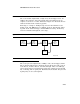
The vector processor has 16 data registers, each containing 64 elements
numbered 0 through 63. Each element is 64 bits wide. A vector
instruction that reads or writes longwords of F_floating or integer data
reads bits <31:0> of each source element and writes bits <31:0> of each
destination element.
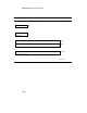
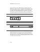
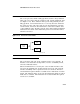
Other registers used with the data registers are the Vector Length, Vector
Count, and Vector Mask Registers (see Figure 2–3). The 7-bit Vector
Length Register (VLR) controls how many vector elements are processed.
VLR is loaded prior to executing a vector instruction. Once loaded, VLR
specifies the length of all subsequent vector instructions until VLR is
loaded with a new value.
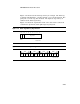
The Vector Mask Register (VMR) has 64 bits, each bit corresponding to
an element in a vector register. Bit <0> corresponds to vector element
zero. The vector mask is used by the vector compare, merge, IOTA, and
all masked instructions.
The 7-bit Vector Count Register (VCR) receives the length of the offset
vector generated by the IOTA instruction.
VLR, VCR, and VMR are read and written by Move From/To Vector
Processor (MFVP/MTVP) instructions.
The Vector Count and Vector Length Registers are in the vector control
unit. The Vector Mask Register and vector data registers are split across
the four vector register file chips.
2–9