
Technical data

Optimizing with MACRO-32
In the following examples, an I represents instruction issue time and an E
represents instruction execution time. A series of periods represents wait
time in the arithmetic unit for deferred instructions. Notice that these
are not exact timing examples, since they do not correspond to individual
instruction timings, but are for illustration purposes only.
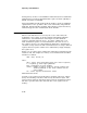
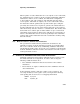
In Example 3–1 the execution of the VLDL instruction does overlap the
VVADDL instruction because there is no conflict in the destination vector
registers, V3 and V1, for the add and load respectively.
Example 3–1 Overlapped Load and Arithmetic Instructions
VVADDL V1,V2,V3 IEEEEEEEE
VLDL base,#4,V1 IEEEEEEEEEEEEEE
3.5.1 Maximizing Instruction Execution Overlap
Three important hardware features help to maximize instruction overlap
in the load/store unit. First, a load or store instruction can execute in
parallel with up to two arithmetic instructions, provided the arithmetic
instructions are issued first. Second, the chain into store sequence can
reduce the perceived execution time of a store instruction. Finally, early
detection of no memory faults allows scalar-to-vector communications to
overlap with load or store instruction execution.
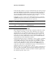
In the first instruction sequence in Example 3–2 there is little overlapping
of instructions, whereas in the second sequence the VVMULL and the
second VLDL instructions overlap and require less total time to complete
execution. The only difference between the two instruction sequences
is the order in which they are issued. Because the VVMULL does not
require the result of the second VLDL and can precede that instruction, a
significant reduction in execution time is achieved.
Another effective way to maximize the overlap of load/store instructions is
to precede, wherever possible, all load and store instructions by at least
two arithmetic instructions. In this way both the load/store pipeline and
the arithmetic pipeline will be in use.
3–16