
Specifications

TURBOchannel Bus Support
12.2 TURBOchannel on DEC 3000 Model 500
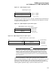
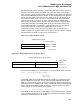
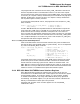
Figure 12–1 Option Register Layout
Option Register Layout
0
slot base + 4 0000
slot base + 4 0004
ZK−6712A−GE
31
register A
register B
If this option was installed in slot 0 in the DEC 3000 Model 500 TURBOchannel,
the option registers would appear at two different physical addresses, as shown
in Figure 12–2 and Figure 12–3.
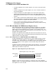
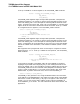
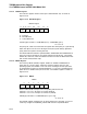
Figure 12–2 Option Register Layout—Dense Space
Option Register Layout − Dense Space
031
register A
register B
1 0004 0000
1 0004 0004
ZK−6713A−GE
physical address
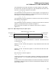
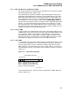
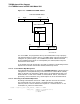
Figure 12–3 Option Register Layout—Sparse Space
Option Register Layout − Sparse Space
031
register A
register B
1 1008 0000
1 1008 0008
ZK−6714A−GE
physical address
mask
mask
3263
Note
Option space addresses are expanded by a factor of two in sparse space.
To convert from a dense space address to an equivalent sparse space
address, set bit 28 of the physical address and shift 26:0 left by one bit.
In sparse space, bits 35:32 of the data longword are used as a byte mask
on write transactions. Byte mask bit set to a 1 causes corresponding data
byte to be written.
The access characteristics of dense space and sparse space are different. In
general, LDL/STL/LDQ/STQ are legal in either dense or sparse space. The main
reason for having sparse space is that it allows the programmer to specify a
byte mask for I/O write transactions, which allows byte write granularity. The
following general guidelines apply to sparse and dense space access:
12–3