
Specifications

TURBOchannel Bus Support
12.2 TURBOchannel on DEC 3000 Model 500
Two TURBOchannel I/O read transactions are issued. Register A and register
B are both read. The data from register A is sign extended and returned in bits
31:0 of R1. The data from register B is discarded.
B.LDQ R1, (R0)
Two TURBOchannel read transactions are issued. Register A and register B are
both read. The data from register A is returned in bits 31:0 of R1, and the data
from register B is returned in bits 63:32 of R1.
C.STL R1, (R0)
Two TURBOchannel write transactions are issued. Bits 31:0 of R1 are written to
both register A and register B.
D.STQ R1, (R0)
Two TURBOchannel write transactions are issued. Bits 31:0 of R1 are written to
register A, and bits 63:32 of R1 are written to register B.
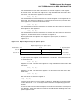
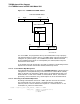
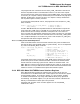
Now suppose that the registers are mapped in sparse space, as shown in
Figure 12–5.
Figure 12–5 Option Register Layout—Sparse Space
Option Register Layout − Sparse Space
031
register A
register B
1 1008 0000
1 1008 0008
ZK−6716A−GE
physical address3263virtual address
base VA
base VA + 8
In sparse space, the register access behaviour is as follows. Assume the base VA
is contained in R0.
A.LDL R1, (R0)
Register A is read. The data from register A is sign extended and returned in bits
31:0 of R1.
B.LDQ R1, (R0)
Register A is read. The data from register A is returned in bits 31:0 and in bits
63:32 of R1.
C.STL R1, (R0)
Bits 31:0 of R1 are stored in register A.
D.STQ R1, (R0)
1-4 bytes of the data in R1 are stored in register A, depending on the byte mask
in bits 35:32 of R1. A "1" in the byte mask causes the corresponding byte to be
written.
As can be seen from the above examples, the access characteristics of each space
are different. These characteristics must be considered when deciding how to do
option register access.
12–5