
Specifications

TURBOchannel Bus Support
12.2 TURBOchannel on DEC 3000 Model 500
12.2.4.1 IOSLOT Register
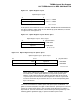
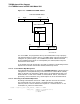
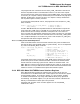
The IOSLOT register contains 3 bits per TURBOchannel slot, as shown in
Figure 12–10.
Figure 12–10 IOSLOT Register
ZK−6721A−GE
0
P B S
slot 0
P B S P B S P B S P B S P B S
slot 5 slot 4 slot 3 slot 2 slot 1
17 15 14 12 11 9 8 6 5 3 2
IOSLOT Register
P − Parity bit
B − Block Mode bit
S − Scatter/Gather bit
IOSLOT physical address: 1 C200 0000 (dense), 1 D400 0000 (sparse)
The parity bit, when set, means that the system will check parity on cycles during
which the option in that slot is driving the bus (the system always generates
parity when the system is driving the bus).
The Block Mode bit enables a specialized DEC 3000 Model 500 TURBOchannel
style of I/O write transactions. No option should ever set this bit. The Scatter
/Gather bit, when set, means that DMA transfers from that TURBOchannel slot
will use the Scatter/Gather map.
12.2.4.2 IMASK Register
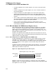
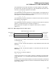
The Interrupt Mask (IMASK) register enables or disables TURBOchannel
interrupts on a per-slot basis. When the console transfers control to the
operating system, the IMASK is set to all ones, meaning that interrupts from
all TURBOchannel slots are masked (disabled). It is up to the TURBOchannel
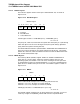
option driver to enable interrupts for its slot. The IMASK register is shown in
Figure 12–11.
Figure 12–11 IMASK
ZK−6722A−GE
0
IMASK
54321
Bits 5:0 enable/disable interrupts from corresponding Turbochannel slot.
When bit is set to a one, interrupts are masked (disabled).
When bit is set to a zero, interrupts are unmasked (enabled).
IMASK physical address: 1 C2400 0000 (dense space only).
The IMASK register should be set up during the driver’s controller or unit init
routine by using the IOC$NODE_FUNCTION routine as explained below.
12–12