
Specifications


TURBOchannel Bus Support
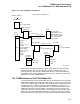
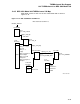
12.2 TURBOchannel on DEC 3000 Model 500
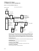
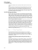
Figure 12–12 DEC 3000 Model 500 ADP List
DEC 3000 Model 500 ADP List
IOC$GL_ADPLIST
adp$ps_child_adp
adp$1_crab
adp$ps_child_adp
adp$ps_peer_adp
System ADP
Turbo ADP
TR = 2
TR = 1
type = AT$_TC
CRAB
Used to manage
type = AT$_KA0402
Scatter/Gather entries.
header
Note: the TurboSCSI
9
entries
header
ADP and the Core ADP
2
entries
SCSI Port A
header
Entry 0 − 5 user
4
SCSI Port B
entries
also contain pointers
Lance
Serial Line 0
TC slots
Serial Line 1
TurboSCSI
Bus Array
ISDN
TurboSCSI ADP
TR = 3
type = AT$_TURBO_SCSI
Entry 6 Integrated
Core
Bus Array
to the CRAB.
SCSI adapter
Core ADP
TR = 4
type = AT$_COREIO
Entry 7 CoreIO
Subsystem
Entry 8 Integrated
Graphics
Turbo
Bus Array
ZK−6723A−GE
After setting up the data structures, INI$IOMAP tests each TURBOchannel slot
for the presence of an option module. For each slot, INI$IOMAP tests the option
ROM base address. If the option responds, INI$IOMAP reads the test pattern
locations in the ROM to verify that the ROM is valid. If the ROM is valid, the
corresponding bus array entry for the TURBOchannel slot is initialized as follows:
BUSARRAY$Q_HW_ID
The Module Name string (8 bytes) is read from the ROM and stored in this field.
BUSARRAY$Q_CSR
The slot base address (sparse space) is stored in this field.
BUSARRAY$L_NODE_NUMBER
The TURBOchannel slot number of the option is stored in this field.
BUSARRAY$L_AUTOCONFIG
The slot interrupt vector is stored in this field.
12–14