
Specifications

PCI Bus Support
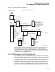
13.1 PCI Addressing
combination of address tricks and CSR control bits to permit access all three
spaces.
The PCI specification recommends that devices be designed such that they can
use memory space for all device registers and device control functions. This
is because Intel processors are only capable of accessing 64 KB of I/O space.
However, there are PCI devices that require both memory space and I/O space.
The example most often cited is a graphics adapter with control registers in I/O
space and a frame buffer in memory space.
13.2 PCI Configuration Space
Every PCI device has its own section of the Configuration Space address space.
Within the device Configuration Space, the device must implement a predefined
header, called the Configuraiton Space header, accessible at offset 0 in the device
Configuration Space. The Configuration Space header contains such information
as Vendor ID, Device ID, Device Class/Type, and Base Address registers. PCI bus
probe routines attempt to read the Vendor and Device ID from the Configuration
Space header of each potential PCI slot on the host PCI bus, in order to discover
which PCI devices are present in the system.
The PCI specification defines a mechanism for accessing the Configuration Space
of all possible PCI devices, whether the devices are on the host PCI (closest to the
CPU), or on a remote PCI accessed through a PCI-PCI bridge. This mechanism
encodes the bus number (0-255, where bus 0 is always the PCI closest to the
CPU), a device number (0-31), and a function number (0-7) to form a unique
Configuration Space address. The device number is analogous to a backplane slot
number, though in reality it is decoded by hardware into a chip select signal for
a single PCI device. Therefore, we can treat PCI as a "slot-based" bus, where we
can find a device based on the bus number and the device slot number.
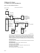
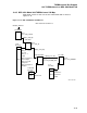
To match the PCI specification of a Configuration Space address, OpenVMS/AXP
defines a PCI node number as follows:
31 16 15 8 7 3 2 0
+-----------------------+---------+---------+-------+
| unused | bus# | device# | func# |
+-----------------------+---------+---------+-------+
Because OpenVMS AXP Version 6.1 does not support PCI-PCI bridges or
multifunction devices, the bus# and function# portions of the PCI node number
are not actually used by any of the PCI bus support routines in OpenVMS
AXP Version 6.1. A future release will include support for PCI-PCI bridges and
multifunction PCI devices.
Although 5 bits are required for the device number, electrical loading
considerations usually limit the number of PCI devices on a bus to less than
32 devices.
The PCI specification defines up to 6 Base Address registers in the Configuration
Space header. The Base Address registers are used to locate the device in the
proper PCI address space (memory or I/O). Bus mapping software reads a Base
Address register to determine how much and what kind of address space a device
requires, and then assigns the base address of the device by writing the Base
Address register. PCI address space assignment is done by the console on AXP
platforms.
13–2