
Specifications


EISA and ISA Bus Support
14.3 EISA Bus Resources
14.3.3 I/O Port Addresses
This resource applies to ISA cards. As mentioned earlier, when the ISA bus
was developed, cards were designed to respond to specific 10 bit addresses. As
ISA became more popular, and vendors increased, the I/O addresses each board
recognized started to overlap. In order to avoid 2 cards answering to the same
I/O address, boards began to provide a jumper to select a range of I/O addresses
they would answer to, increasing flexibility of configuration. Thus the ECU
is responsible for assigning ISA boards an I/O Port starting address. See the
System Address Map in a later section for a description of the available ISA I/O
ports. EISA cards generally do not need to have I/O ports assigned to them as
they can do geographical slot-based addressing using the AENx signal in the
EISA protocol.
14.3.4 EISA Memory Addresses
On some PC machines, system memory is accessed directly over the EISA bus.
On Digital machines, the EISA bus is used as an I/O bus. Digital machines
provide access to EISA memory space to access 00 on-board memory, such as
frame buffers, on some EISA option cards. See the System Address Map in a
following section for a description of these address ranges.
14.3.5 EISA Configuration Utility
The ECU is a standalone program that is run prior to booting the machine. The
purpose of the ECU is to assign resources to all the cards plugged into the EISA
bus in a conflict free manner. The ECU uses configuration files (.CFG files) to
get resource requirements for the EISA devices in the system, and prompts for
user input to get resource requirements for the ISA devices in the system. The
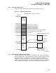
EISA protocol added a software readable ID at a predefined offset on the board
( C80-C83). The board manufacturer is free to choose any ID they want for
the offset, but, typically, companies are assigned a 3 letter code which uniquely
identifies their boards. It is then up to the manufacturer to keep track of its
own IDs so that each board is uniquely identifiable. For details on the contents
of the configuration files, see the EISA spec. The .cfg file contains initialization
information and resource requirements. The ECU writes all the configuration
data, including initialization urp information to NVRAM. It is up to the firmware
operating system to use this configuration initialization information. It then
determines the requirements of all the options and find a conflict free assignment
of the resources if possible. If the ECU cannot find a conflict free assignment
of resources, it indicates that a different configuration must be used. The ECU
also has the capability of prompting the user to enter configuration information
about ISA cards, which typically have no configuration information files. The
ECU then writes the configuration information into NVRAM on the system board,
using console (or BIOS) callback routines. This information in NVRAM is made
available to the drivers via the operating system. (IOC$NODE_FUNCTION,
IOC$NODE_DATA are the routines provided by OpenVMS AXP). After writing
the configuration information to NVRAM, the ECU instructs the user to power
off the system, set any jumpers/switches on the ISA boards, remove the ECU
diskette, and power on. At this point the drivers must call the available routines
to determine which resources they have been assigned. Note that the ECU need
only be run when the system configuration is changed, that is, when boards are
added, deleted, or moved around in the EISA slots. It is not necessary to run the
ECU before each boot, as the configuration is stored in NVRAM.
14–3