
Specifications


EISA and ISA Bus Support
14.4 EISA Interrupts
14.4 EISA Interrupts
The interrupt mechanism on EISA is designed around the requirements of the
INTEL 8259 interrupt controller chip. An EISA I/O adapter is designed to work
using a small subset of the available interrupt levels on EISA. The cards are
designed this way to allow many different configurations to be supported. What
this means to the driver writer is you need a method of finding out which IRQ
has been assigned to the board so that you can program the board to work with
the IRQ (or set a jumper if the board is an ISA board). The IOC$NODE_DATA
routine provides this functionality and is described in a later section.
The following is an overview of the sequence of events surrounding an EISA
device interrupt.
• The EISA Device requires an interrupt, and asserts the programmed EISA
irq line. These lines can be programmed for either edge-triggered (active
high) or level-sensitive (active low for sharing irqs) mode.
• The 82357 sees at least one bit in the Interrupt Request Register go high and
sets an interrupt pin on the CPU.
• PALcode is invoked and determines that the interrupt is an EISA I/O
interrupt
• An INTA (Interrupt Acknowledge) command is sent out over the EISA bus to
the 82357.
• This INTA causes the 82357 to lock the Interrupt Request Register for
prioritization of the requesting interrupts, and sets a bit in the In Service
Register denoting the interrupt selected for service.
• The CPU sends another INTA command over the bus to the 82357, and this
command causes a vector identifying the highest priority IRQ requesting
service to be sent back over the EISA bus to the CPU.
• PALcode recieves the vector and vectors through the appropriate SCB vector.
• The Driver Interrupt Service Routine services the interrupt and returns to
the Operating System Support EISA support code.
• The EISA support code then issues an End Of Interrupt (EOI) command to
the 82357 which clears the In Service Register, allowing interrupts of equal
and lower priority to occur again. This EOI command is done automatically
by Bus Support code in OpenVMS AXP. Operating system code then REIs
back to the interrupted thread. Note that if software does not perform the
EOI, all future interrupts of equal or lower priority will be disabled.
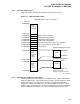
14.5 EISA DMA Support
The 82357 Chip provides 7 independently programmable DMA channels for use
by EISA/ISA cards that do not have Bus Master capability, and cannot drive
the necessary signals to perform DMA on their own. These seven channels are
implemented using the logic of 2 INTEL 8237 chips, with one cascading into the
other (Channel 4 is used to cascade the two controllers together). Any channel
can be programmed for 8, 16, or 32 bit DMA device size, and ISA compatible
"type a", "type b", or burst dma "type c" modes. The EISA Bus Controller chip
handles the data size translation. The DMA addressing circuitry supports full 32
bit addresses for DMA devices. Each channel includes a 16 bit Current register,
a low Page register and a high page register. Both page registers are 8 bits,
and between the 3 cover the 32 bits. The channels can be programmed for one
14–4