
Specifications

Futurebus+ Bus Support
15.3 Futurebus+ CSR Addressing
Core, Futurebus+ Dependent, ROM, and Initial Units Space. The CSR Core
space is defined by IEEE 1212 (CSR Architecture). Futurebus+ Dependent space
is defined by IEEE 896.2 (Physical Layer and Profile). ROM space is defined by
both IEEE 1212 and 896.2. Initial Units Space is vendor defined.
[LIB.LIS]FBUSDEF.SDL defines symbolic register offsets for the 4KB initial node
space.
15.4 CSR Data Format
CSR register definitions for the CSR Core, Futurebus+ Dependent, and ROM
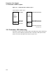
area are given in IEEE 1212 and 896.2 in "big-endian" data format. Big-endian
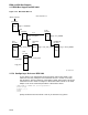
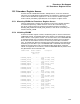
register data format is specified as shown in Figure 15–3.
Figure 15–3 Big-Endian Register Data Format
ZK−6728A−GE
0 157 8 23 16 31 24
byte 0 byte 1 byte 2 byte 3
Big−endian register data format
Most Significant
Byte
Least Significant
Byte
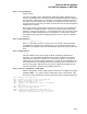
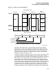
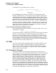
Little-endian register format is defined as shown in Figure 15–4.
Figure 15–4 Little Endian Register Data Format
ZK−6729A−GE
24 2331 16 15 8 7 0
byte 3 byte 2 byte 1 byte 0
Little−endian register data format
Most Significant
Byte
Least Significant
Byte
When a big-endian register is driven onto the Futurebus+, byte 0 is driven
on Futurebus+ AD<7:0>, byte 1 is driven on AD<15:8>, byte 2 is driven on
AD<23:16>, and byte 3 is driven on AD<31:24>. FBUSDEF.SDL defines CSR
Core, Futurebus+ Dependent, and ROM registers in little-endian format, thus,
byte lane swapping must be performed after reading and before writing registers
in the CSR Core, Futurebus+ Dependent, and ROM areas in order to make the
register data match the FBUSDEF.SDL definitions. In general a driver has no
need to access registers in the CSR Core, Futurebus+ Dependent, or ROM areas.
These areas are primarily used for initial node setup and are only accessed
during booting and system configuration. Initial Unit Space is vendor-defined, so
registers in Initial Unit Space may be either big or little endian. Digital adapters
generally use little-endian register definitions for Initial Unit Space registers.
15–4