
Specifications
Futurebus+ Bus Support
15.5 Futurebus+ Register Access
An example call to IOC$CRAM_CMD is as follows:
status = ioc$cram_cmd(cramcmd$k_rdlong32, /*
command index */
4, /* byte offset */
adp_address,
cram_address);
The COMMAND field bit patterns are stored in a table pointed to by field
ADP$PS_COMMAND_TBL in the Futurebus+ ADP. IOC$CRAM_CMD uses the
command index to find the proper COMMAND field bit pattern, and copies the
command field bits to CRAM$L_COMMAND. RBADR is calculated from the byte
offset input parameter and the IDB$Q_CSR field in the IDB. The byte offset is
added to the value in IDB$Q_CSR, and the result is copied to CRAM$Q_RBADR.
No further alignment is applied to RBADR. The MASK field is calculated based
on the command index and the byte offset. If the caller specifies a byte or word
length read or write, the MASK bits are set based on the transfer size (byte or
word) and the first byte involved in the transfer.
15.5.3 Issuing the Futurebus+ Register Access
There is nothing specific to the Futurebus+ in issuing the CRAM. A driver calls
IOC$CRAM_IO, as follows:
status = ioc$cram_io (cram_address);
On Futurebus+ platforms, IOC$CRAM_IO performs the entire Alpha I/O mailbox
operation, including queueing the mailbox and waiting for the DONE bit. A
driver may also call IOC$CRAM_QUEUE, which queues the hardware mailbox
and returns to the caller without waiting for the DONE bit to be set. If a driver
uses IOC$CRAM_QUEUE, the driver should call IOC$CRAM_WAIT to check
that the DONE bit is set (indicating the previous operation has completed) before
re-using the CRAM for another register access.
15.6 DMA
On the DEC 4000 and DEC 10000/7000 platforms, Futurebus+ adapters access
system memory through the Futurebus bridge. The bridge accepts all non-
register space Futurebus+ addresses, and passes them directly to the system
memory. There are no map registers in either DEC 4000 or DEC 10000/7000,
hence all DMA is "physical" DMA.
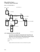
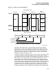
15.7 Futurebus+ Interrupts
A Futurebus+ adapter interrupts the host by writing a 32 bit quantity (an
interrupt vector) to an Interrupt Request register address. The Interrupt Request
register address is not specified by the Futurebus+ specifications–it is left up
to system implementors to define the interrupt mechanisms for a particular
system. Digital Futurebus+ bridges implement 4 Interrupt Request register
addresses at offsets 800, 804, 808, and 80C (hex) in the bridge’s Initial Unit
Space. Futurebus+ adapters generally implement an Interrupt Target and
an Interrupt Vector register in the adapter Initial Unit Space. During driver
initialization, the driver writes the adapter Interrupt Target register with the
address of one of the bridge’s Interrupt Request registers, and writes the adapter
Interrupt Vector register with the assigned interrupt vector (the adapter interrupt
vector is assigned when the driver is loaded). The Futurebus+ adapter interrupts
the host by writing the value in its Interrupt Vector register to the address stored
in its Interrupt Target register. This is shown in Figure 15–5.
15–6