
Specifications

Futurebus+ Bus Support
15.9 Configuring a Futurebus+ Adapter
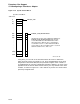
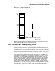
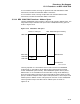
Figure 15–7 System Control Block
System Control Block
SCB offset
800
810
820
0
10
20
1FE0
1FF0
.
.
.
.
.
.
.
.
.
.
.
.
.
.
.
ZK−6732A−GE
OpenVMS/AXP vector assignments
Manually configured Futurebus+ adapter
vector assignments
Note that interrupt vectors assigned using SYSMAN IO CONNECT commands
will not be reflected in the SCB Reservation bitmap.
15.10 Futurebus+ Bus Probing During Booting
During booting, INI$IOMAP constructs an ADP list that represents the I/O
adapters present in the system. For the Futurebus+, an ADP (representing the
Futurebus+ bridge) and associated Bus Array are allocated. The size of the
Futurebus+ Bus Array is based on the number of physical Futurebus+ backplane
slots. The bus array is made large enough to contain an entry for the maximum
number of Futurebus+ nodes that could be present in the system, which is twice
the number of physical backplane slots.
After setting up the Futurebus+ bridge ADP and Bus Array, INI$IOMAP tests
each potential Futurebus+ node to determine if an adapter is present. For each
Futurebus+ node, INI$IOMAP reads the TEST_STATUS register in Core CSR
space. If the node responds, INI$IOMAP then reads locations in the node ROM
space to identify the node. Specifically, INI$IOMAP searches node ROM space
for a ROM location that identifies the module manufacturer. Normally this
will be one of MODULE_VENDOR_ID or NODE_VENDOR_ID (the Futurebus+
specifications say that only one of these locations should be present in the ROM).
The Futurebus+ specifications also define MODULE_SPEC_ID, NODE_SPEC_ID,
and UNIT_SPEC_ID for the case when a board from manufacturer X requires
15–11