
Installation guide


Unpacking and Assembling Cabinets 2-37
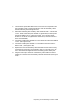
WARNING: Before beginning this procedure, ensure that the system is
powered off.
1. Plug one end of the power control cable into the jack marked Left Ex-
pander located on the top right of the system cabinet as viewed from
the front. If a second expander cabinet is installed, plug another
power control cable into the jack marked Right Expander.
2. Route each power control cable through a cable routing channel to the
rear of the system cabinet and into the top of the expander cabinet(s)
as illustrated in Figure 2-19.
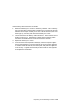
3. Remove the CCL module access plate on each expander cabinet. The
access plate is located in the upper top left (as viewed from the rear)
of the expander cabinet. Remove the plate by removing three screws.
4. Plug the other end of each power control cable into jack J2 located on
the upper right of the CCL module.
5. Replace each CCL module access plate by replacing the three screws.
Figure 2-19 Power Control Cable Routing
BXB-0021E-92
System
Cabinet
Rear
System
Cabinet
Front
Expander
Cabinet
Rear