
Installation guide


Connecting to a DSSI Subsystem 4-11
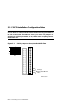
1. XMI Node Number
Locate the XMI slot of the KFMSA-BA by looking in the XMI card
cage. The XMI node number and physical slot number are the same.
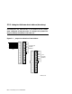
2. DSSI Bus Number
Each KFMSA-BA module has two separate DSSI buses (ports) cabled
from XMI backplane sections D and E. The cable from section D (up-
per section) is designated as bus 1, and the cable from section E is bus
2. Each bus presents a discrete set of registers to the host. Note that
for communication to occur, the host software must identify which
DSSI bus is attached to which ISE. Use the color-coded labels (from
the KFMSA Module Installation and User Manual) at each connector
end of a cable to make maintenance easier. Record the label colors on
the configuration sheet, also found in the manual.
When attaching the cables to a disk PIU:
1. Open the cabinet door.
2. For each populated bus, install one external cable to one of the
KFMSA-BA disk controller ports. Tighten the two screws that secure
each cable to the XMI I/O bulkhead.
3. If the system has more than one KFMSA-BA adapter, install addi-
tional DSSI cables to the XMI I/O bulkhead, as above.
4. Install terminators where needed.
For more information:
KFMSA Module Installation and User Manual